
How to Build a Smart Traffic Control System Using Image Processing
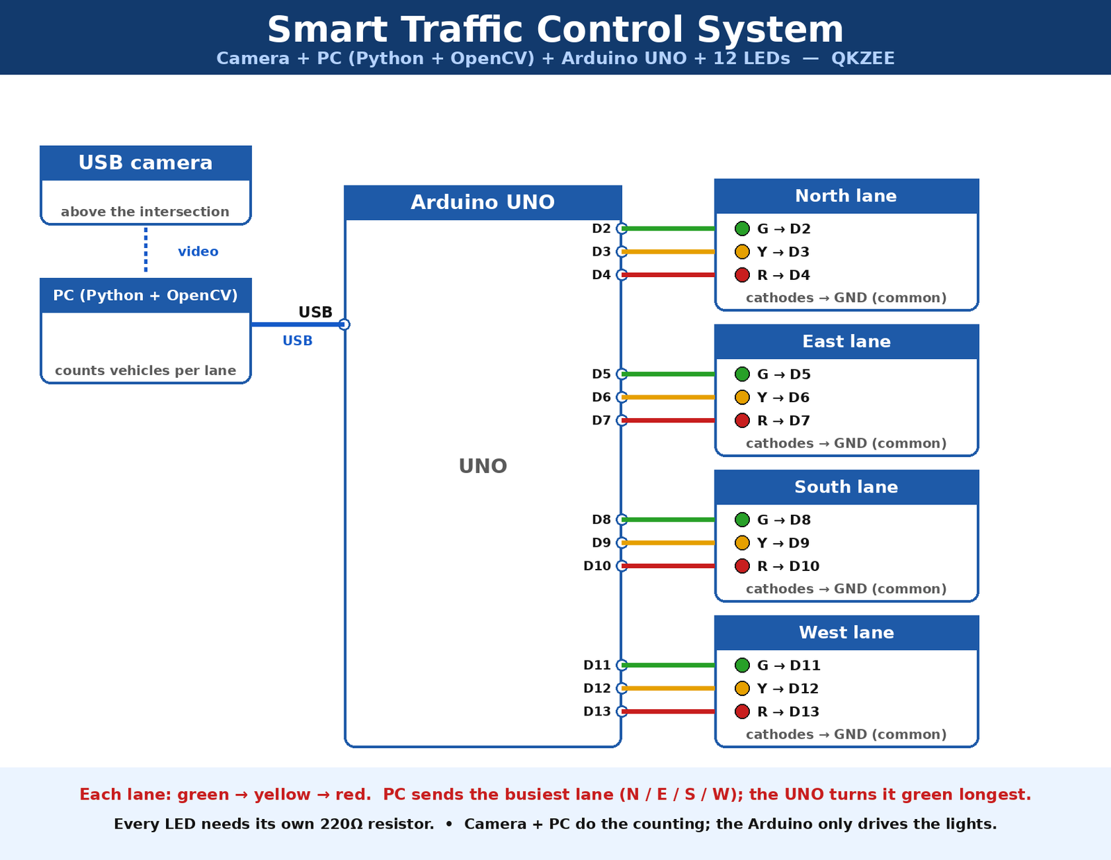
A smart traffic control system uses a camera and image processing instead of traditional timers or simple sensors. By capturing real-time images of each road lane, it measures vehicle density and adjusts signal timings: the busiest lane stays green longest. This guide builds the system in two parts — a PC runs Python with OpenCV to count vehicles per lane, and an Arduino UNO drives the traffic lights (12 LEDs, 4 lanes × red/yellow/green). It is a popular final year project for students in Pakistan because it combines computer vision, serial communication and microcontroller control in one working model.
How the System Works
- A USB camera mounted above the intersection streams video to a PC.
- The PC divides each frame into four lane regions (North, East, South, West) and counts vehicles in each one using background subtraction — it compares the current frame with an empty-road reference and counts the moving blobs.
- The PC sends the counts to the Arduino over USB serial as one line, for example
N:2 E:1 S:0 W:3. - The Arduino picks the busiest lane, turns it green longest, and keeps the other lanes red — with a yellow light before every change.
Instead of a fixed cycle, the lights adapt to traffic flow, which reduces waiting time and vehicle emissions.
Main Components Needed
| Component | Price / link |
|---|---|
| Arduino UNO R3 DIP | Arduino UNO R3 DIP ATmega328P with USB Cable — Rs 1,200 |
| 5mm diffused LED × 12 (4 red, 4 yellow, 4 green) | 5mm Diffused LED — Red, Yellow, Green, Blue, White — Rs 6 each |
| 220Ω resistor × 12 (one per LED) | No QKZEE listing — available at the Hall Road shop on request |
| MB102 breadboard (for testing on the bench) | MB102 Breadboard 830 Points — Rs 250 |
| 40-pin jumper wires | 40-Pin Jumper Wires 30cm — Rs 180 |
| USB webcam | No QKZEE listing — any USB webcam works |
| Windows/Linux PC (or Raspberry Pi) | Your own computer |
| HC-SR04 ultrasonic sensor (optional, for a sensor-based version) | HC-SR04 Ultrasonic Sensor — Rs 200 |
| ESP32 board (optional, for the IoT version) | ESP32 30 Pin WiFi + Bluetooth Development Board — Rs 1,100 |
| NodeMCU ESP8266 (optional, cheaper Wi-Fi option) | NodeMCU ESP8266 CH340 WiFi Board — Rs 590 |
A Raspberry Pi can replace the PC (it runs Python + OpenCV too, more slowly) — there is no QKZEE listing for it.
Wiring
Traffic Light LEDs → Arduino
Each LED’s anode (long leg) goes to its Arduino pin through its own 220Ω resistor. All cathodes (short legs) go to the common GND rail.
| Lane | Green | Yellow | Red |
|---|---|---|---|
| North | D2 | D3 | D4 |
| East | D5 | D6 | D7 |
| South | D8 | D9 | D10 |
| West | D11 | D12 | D13 |
Camera and PC → Arduino
| Connection | How |
|---|---|
| USB camera → PC | USB cable — the camera streams video to the PC |
| PC → Arduino | USB cable — the PC sends the lane counts as serial text |
The Arduino is powered and programmed through the same USB cable. No separate power supply is needed for the LED model (each LED draws only ~15 mA through its resistor).
Required Software
On the PC, install Python, then these two packages:
pip install opencv-python pyserialopencv-python gives you OpenCV (image processing); pyserial lets Python talk to the Arduino over USB. On the Arduino side, no extra libraries are needed — the sketch uses only the built-in Serial functions.
Complete Python Code (Vehicle Counting)
"""
Smart Traffic Control — PC side (Python + OpenCV)
Counts vehicles in four lane regions and sends the counts to the
Arduino as one line:  N:2 E:1 S:0 W:3
Test it on a recorded video first, then on the live webcam.
Needs:  pip install opencv-python pyserial
"""

import cv2
import serial
import time

# --- settings: change these for your own video ---
VIDEO = 0                  # 0 = webcam, or 'traffic.mp4' for a recorded video
SERIAL_PORT = 'COM3'       # Windows: 'COM3'; Linux: '/dev/ttyACM0'
BAUD = 9600
MIN_AREA = 500             # ignore blobs smaller than this (noise/shadows)

# Lane regions as fractions of the frame (x, y, w, h) — adjust to your camera view
LANES = {
    'N': (0.05, 0.05, 0.40, 0.40),
    'E': (0.55, 0.05, 0.40, 0.40),
    'S': (0.05, 0.55, 0.40, 0.40),
    'W': (0.55, 0.55, 0.40, 0.40),
}

cap = cv2.VideoCapture(VIDEO)
back_sub = cv2.createBackgroundSubtractorMOG2(history=200, varThreshold=50)
ser = serial.Serial(SERIAL_PORT, BAUD, timeout=1)
time.sleep(2)   # let the Arduino reset

while True:
    ok, frame = cap.read()
    if not ok:
        break
    gray = cv2.cvtColor(frame, cv2.COLOR_BGR2GRAY)
    mask = back_sub.apply(gray)
    _, mask = cv2.threshold(mask, 200, 255, cv2.THRESH_BINARY)
    mask = cv2.morphologyEx(mask, cv2.MORPH_OPEN,
                            cv2.getStructuringElement(cv2.MORPH_ELLIPSE, (5, 5)))

    counts = {}
    h, w = gray.shape
    for name, (fx, fy, fw, fh) in LANES.items():
        x, y, ww, hh = int(fx * w), int(fy * h), int(fw * w), int(fh * h)
        roi = mask[y:y + hh, x:x + ww]
        contours, _ = cv2.findContours(roi, cv2.RETR_EXTERNAL, cv2.CHAIN_APPROX_SIMPLE)
        n = sum(1 for c in contours if cv2.contourArea(c) > MIN_AREA)
        counts[name] = n
        cv2.rectangle(frame, (x, y), (x + ww, y + hh), (0, 255, 0), 2)
        cv2.putText(frame, f"{name}:{n}", (x + 10, y + 30),
                    cv2.FONT_HERSHEY_SIMPLEX, 0.8, (0, 255, 0), 2)

    line = " ".join(f"{k}:{v}" for k, v in counts.items())
    ser.write((line + "\n").encode())
    print(line)

    cv2.imshow("Traffic", frame)
    if cv2.waitKey(30) & 0xFF == ord('q'):
        break

cap.release()
cv2.destroyAllWindows()
Complete Arduino Code (Traffic Lights)
/*
  Smart Traffic Control — ARDUINO UNO side
  Receives "N:2 E:1 S:0 W:3" from the PC over USB serial, picks the
  busiest lane, and turns it green longest (5 s + 1 s per vehicle,
  capped at 15 s). Every change goes through yellow first.
  Pins: North G D2 Y D3 R D4 | East G D5 Y D6 R D7
        South G D8 Y D9 R D10 | West G D11 Y D12 R D13
*/

const int lanePins[4][3] = {
  {2, 3, 4},    // North: G, Y, R
  {5, 6, 7},    // East:  G, Y, R
  {8, 9, 10},   // South: G, Y, R
  {11, 12, 13}  // West:  G, Y, R
};
const char laneNames[4] = {'N', 'E', 'S', 'W'};

void setup() {
  Serial.begin(9600);
  for (int lane = 0; lane < 4; lane++)
    for (int c = 0; c < 3; c++)
      pinMode(lanePins[lane][c], OUTPUT);
  allRed();
}

void loop() {
  if (Serial.available()) {
    String line = Serial.readStringUntil('\n');
    line.trim();
    int counts[4] = {0, 0, 0, 0};
    for (int lane = 0; lane < 4; lane++) {
      int i = line.indexOf(laneNames[lane]);
      if (i >= 0) counts[lane] = line.substring(i + 2).toInt();
    }
    int busiest = 0;
    for (int lane = 1; lane < 4; lane++)
      if (counts[lane] > counts[busiest]) busiest = lane;
    int greenTime = 5000 + counts[busiest] * 1000;
    if (greenTime > 15000) greenTime = 15000;
    runLane(busiest, greenTime);
  }
}

void setLane(int lane, bool g, bool y, bool r) {
  digitalWrite(lanePins[lane][0], g ? HIGH : LOW);
  digitalWrite(lanePins[lane][1], y ? HIGH : LOW);
  digitalWrite(lanePins[lane][2], r ? HIGH : LOW);
}

void allRed() {
  for (int lane = 0; lane < 4; lane++) setLane(lane, false, false, true);
}

void runLane(int lane, int greenTime) {
  allRed();
  setLane(lane, false, true, false);   // yellow first
  delay(2000);
  setLane(lane, true, false, false);   // green
  delay(greenTime);
  setLane(lane, false, true, false);   // yellow again
  delay(2000);
  allRed();
}
What the Code Does
- The Python script grabs video frames, converts them to grayscale, and runs background subtraction (MOG2) — it compares each frame with an empty-road reference and keeps only the moving blobs. Small blobs below
MIN_AREAare ignored as noise or shadows. - Each frame is split into four lane regions. Inside each region it counts the blobs big enough to be vehicles, draws a green box with the count on the video, and sends one line of counts to the Arduino.
- The Arduino sketch reads the line, finds the busiest lane, and runs it: all red, then yellow for 2 seconds, then green for 5 seconds plus 1 second per vehicle (capped at 15 seconds), then yellow again. If all lanes are empty it defaults to North.
- Press
qin the video window to stop the Python script.
How to Make the Traffic Model
Step 1: Gather Materials
Get the camera, Arduino, 12 LEDs, 12 resistors, wires and a computer. The LEDs, Arduino and wires are available at QKZEE Technologies on Hall Road, Lahore — see the links above.
Step 2: Set Up the Hardware
Wire the 12 LEDs to the Arduino as in the table above, each through its own 220Ω resistor, cathodes to the common GND rail. Test each LED with a simple blink program to confirm the wiring. Mount the camera so it has a clear view of all four lanes.
Step 3: Develop the Software
Install Python, OpenCV and pySerial. First test the vehicle counting on a recorded video, adjusting the lane regions and MIN_AREA so cars are detected and shadows are not. Then upload the Arduino sketch.
Step 4: Integrate and Test
Connect the camera to the PC and the Arduino via USB. Run the Python program and send the counts to the Arduino. Verify that the traffic lights respond correctly — simulate traffic with toy cars or a video. Debug any timing or detection issues.
Step 5: Refine
Improve accuracy by calibrating the camera position and lighting conditions. Add error handling: for instance, if the camera feed is lost, revert to a default timer mode. Keep your paragraphs short and document all circuits and code for the final project report.
Testing the System
- Test the LEDs first. Upload a blink sketch and check all 12 LEDs light up. If one does not, check its resistor and that its cathode goes to GND.
- Test the counting on a video. Run the Python script on a recorded traffic video and watch the lane boxes — the counts should rise when cars pass. If shadows are counted as cars, raise
MIN_AREA. - Test the serial link. Open the Arduino Serial Monitor at 9600 baud while the Python script runs — you should see lines like
N:2 E:1 S:0 W:3. If nothing appears, check the COM port in the Python script. - Test the lights. With the Python script running, the busiest lane’s green LED should stay on longest. If the lights never change, the Arduino is not receiving — check the USB cable and the port.
Troubleshooting
- Shadows counted as vehicles: raise
MIN_AREAin the Python script, or run the test in even lighting. Shadows are the most common cause of false counts. - No counts at all: check the lane regions match your camera view — the green boxes drawn on the video show where each lane is. If a lane box sits on empty road, move it.
- Arduino lights never change: check the Serial Monitor shows the count lines. If it does, the fault is in the Arduino sketch; if it does not, the fault is in the Python script or the COM port.
- LEDs very dim or not lighting: check each LED has its own 220Ω resistor and the cathode goes to GND. A missing resistor can also damage the LED or the Arduino pin.
- Camera feed lost: the Python script stops on a failed frame read. Add the default-timer fallback: if no frame arrives for 5 seconds, run a fixed cycle on the Arduino instead.
Performance Results
Published results for this kind of system are honest about the conditions. In one reported test, 13 vehicles passed and all 13 were detected. In another scenario with 8 vehicles, 6 were correctly detected — some shadows were misclassified (6 out of 8 is 75%). So the system can be very accurate in good light, but shadows and poor camera angles lower it. Do not claim 100% accuracy for your own build — report what your tests actually measured, and say under which conditions.
IoT Integration and Advanced Features
The project extends naturally into IoT: add an ESP32 or NodeMCU and upload the lane counts to ThingSpeak or Firebase, creating a real-time dashboard of traffic flow for smart-city analytics. We use the same ThingSpeak approach in our IoT smart parking guide — the ESP32 sketch there sends a single number to field1, and the same pattern works for four lane counts (one field per lane). You can also build a mobile interface with Blynk, or program an emergency-vehicle override: if an ambulance signal is detected, that lane is prioritised immediately.
Variations and Related Projects
- DLD (Digital Logic Design): a simplified version using hardware gates and timers, where sensor inputs (instead of images) mimic vehicle counts.
- Arduino/Robotics: start with a 3-LED traffic light kit, then add a camera or ultrasonic sensors to make it “smart”.
- Raspberry Pi projects: a Raspberry Pi with a camera and OpenCV runs the whole system in one box, and can add machine learning (for example YOLO object detection) to identify vehicles.
- Biomedical/science models: the same image analysis (background subtraction, counting objects) is used in medical imaging, like counting cells in a microscope slide.
Where to Buy the Components
The Arduino UNO, 5mm LEDs, HC-SR04 sensor, ESP32 board, NodeMCU, breadboard and jumper wires are available at QKZEE Technologies, Shop 20, 1st Floor, Al-Khalil Center, Hall Road, Lahore, and online at qkzeetech.com with delivery all over Pakistan — see the links above. The USB webcam, Raspberry Pi and 220Ω resistors are available at the Hall Road shop on request.
Still Stuck?
If the counting does not work, or the lights never change, message us — tell us what the Python window shows and what the Serial Monitor prints, and we will help you find the fault.
FAQs
Do I need a powerful PC for this?
No — any ordinary laptop runs OpenCV on a webcam feed. A Raspberry Pi works too, more slowly. Start by testing on a recorded video, which needs even less power.
Why does the system count shadows as cars?
Background subtraction sees any change from the empty-road reference, including shadows. Raising MIN_AREA, testing in even light, and mounting the camera high all reduce false counts.
Can I use a Raspberry Pi instead of a PC + Arduino?
Yes — the Pi runs Python + OpenCV and can drive the LEDs directly from its GPIO pins, so the Arduino is not needed. The PC + Arduino version is easier to debug one part at a time.
What if I have no camera?
Use the HC-SR04 ultrasonic sensor version instead: one sensor per lane measures whether a car is present, and the same Arduino sketch logic applies. The counting is simpler but there is no image processing.
Can the system handle an ambulance?
Yes, as an extension: add a sound sensor or an RFID tag for the ambulance lane, and when it triggers, give that lane green immediately regardless of the counts.
Why 220Ω resistors for the LEDs?
An LED without a resistor draws too much current and can burn out — and can damage the Arduino pin driving it. 220Ω limits a 5V-driven LED to about 15 mA, which is safe for both.
Conclusion
A smart traffic control system using image processing is a comprehensive electronics and automation project. By combining a camera, image analysis and microcontroller-driven lights, you can build an advanced final year project that outranks simple timer-based controllers. The guide above covers the hardware circuits, both code listings, and the IoT enhancements needed to implement it successfully. Test it on video first, measure your own accuracy honestly, and document every step for your project report.