How to Make an Automatic Night Light Switch with LDR and LM358 (No Arduino Needed)
A light that switches itself on the moment it gets dark, and switches itself off again when morning comes — that is what an automatic night light switch does. This project needs no Arduino and no code. Just an LDR sensor, an LM358 IC, a transistor and a few small components.
This project is ideal for school and college students in Pakistan — for a science exhibition, FYP (final year project) preparation, or for use at home. You can use it as a room, stairs, study table or corridor light. It runs on a 9V battery, so it keeps working even during load shedding.
How Does It Work?
The circuit works in three parts:
- The LDR sensor measures light. The LDR (Light Dependent Resistor) is a sensor whose resistance changes with light. In bright light its resistance drops, and in darkness it becomes very high.
- The LM358 decides. The LDR and the 10k resistor form a voltage divider. The divider voltage goes to pin 3 of the LM358. On the other side, the 10k variable resistor (pot) creates a reference voltage that goes to pin 2. The LM358 compares the two voltages — when it gets dark, the pin 3 voltage rises above the reference and the LM358 output (pin 1) goes HIGH.
- The transistor switches the light on. The LM358 output goes through a 1k resistor to the base of the C945 transistor. As soon as the output goes HIGH, the transistor turns on and the LED light module gets current — the light turns on. In bright light the output goes LOW, the transistor turns off, and the light goes off.
Turning the 10k variable resistor lets you set how dark it must be before the light turns on — that is the sensitivity setting of this circuit.
Components Needed
| Component | Quantity | Price / Notes |
|---|---|---|
| LDR Light Sensor Module | 1 | Rs 130 — the diagram uses a bare LDR sensor; this module is also based on an LDR |
| 9V Rechargeable Battery with Clip Connector | 1 | Rs 120 |
| ON/OFF Rocker Switch | 1 | Rs 30 |
| MB102 Breadboard 830 Points | 1 | Rs 250 |
| 5mm Diffused LED (Red) | 1 | Rs 6 — for the power indicator |
| 40-Pin Dupont Jumper Wires 30cm | 1 pack | Rs 180 |
| LM358 IC | 1 | Available in the shop — contact us on WhatsApp for the price |
| C945 NPN Transistor | 1 | Available in the shop — contact us on WhatsApp for the price |
| 1k Resistor | 2 | Available in the shop — contact us on WhatsApp for the price |
| 10k Resistor | 1 | Available in the shop — contact us on WhatsApp for the price |
| 10k Variable Resistor (Preset/Pot) | 1 | Available in the shop — contact us on WhatsApp for the price |
| LED Light Module (as shown at the bottom of the diagram) | 1 | Available in the shop — contact us on WhatsApp for the price |
(Prices are from November 2026 — check the product page for the latest price. Delivery is a flat Rs 350 all over Pakistan, 3–4 working days.)
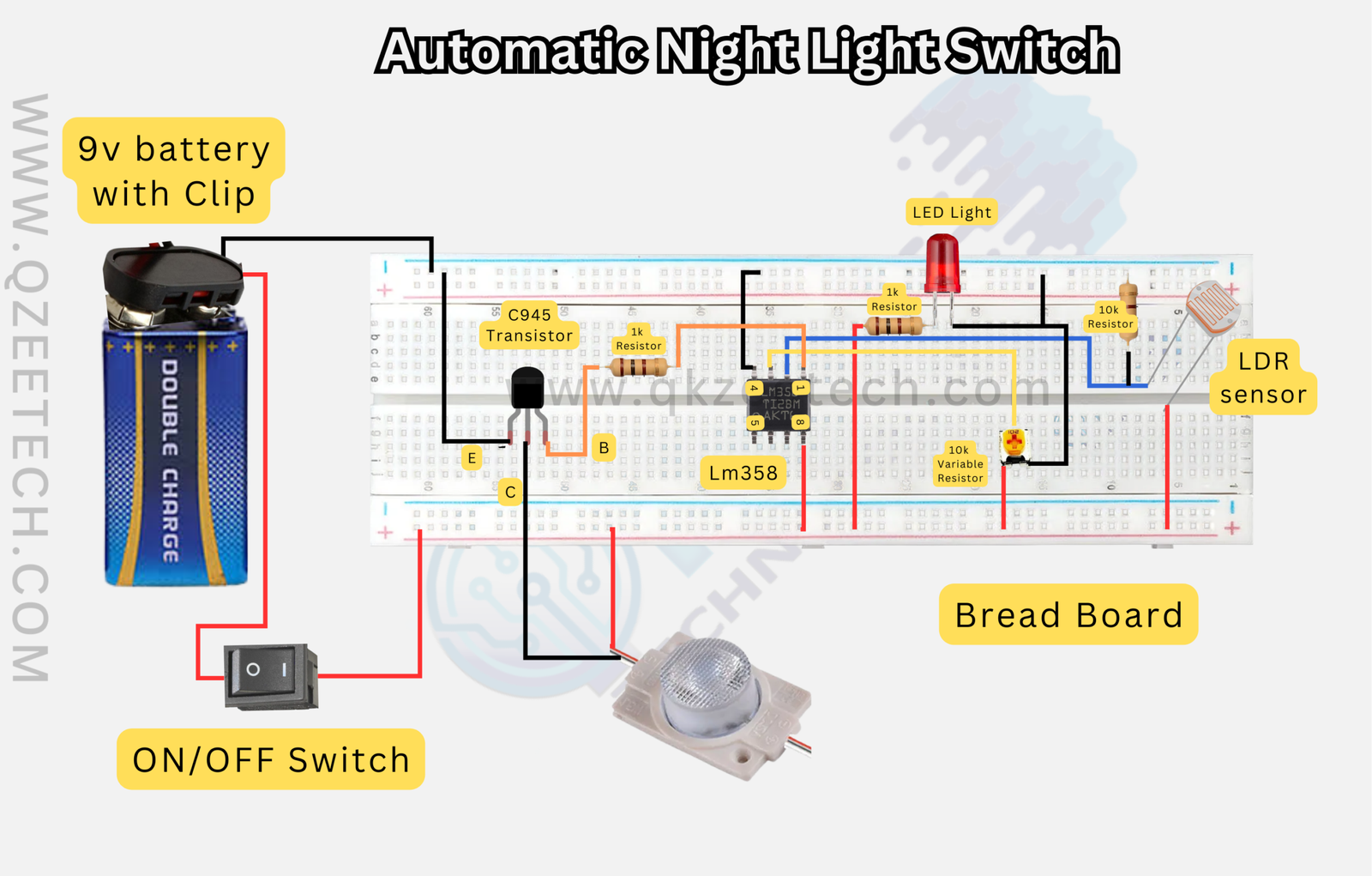
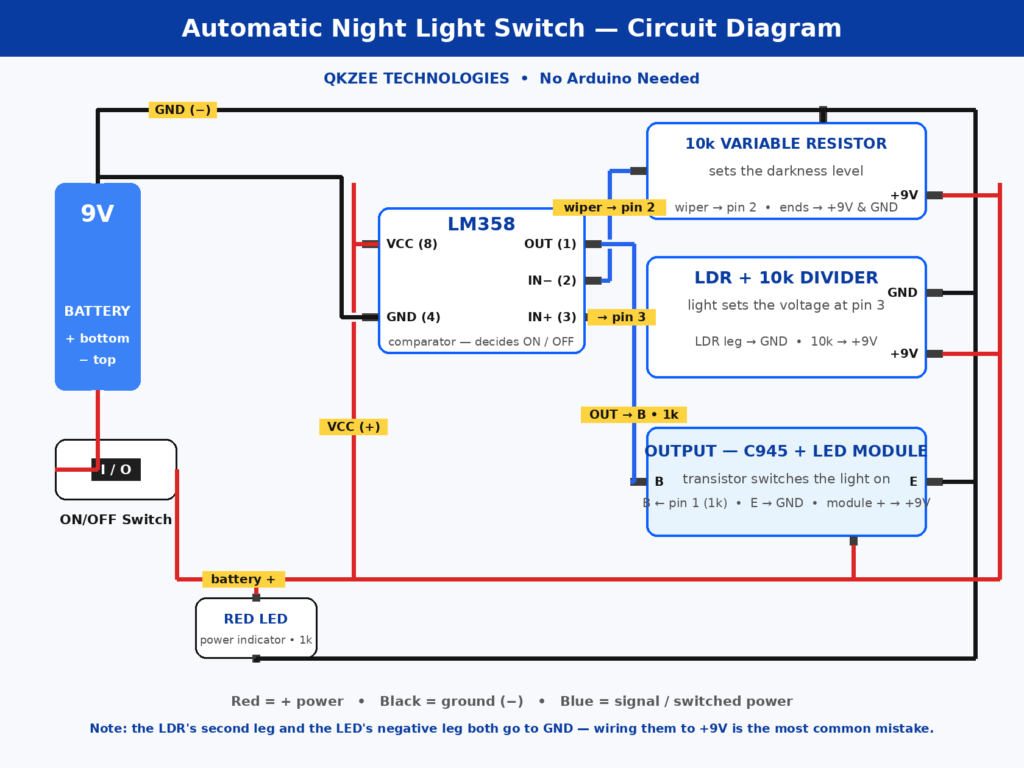
Circuit Diagram
Connections — Step by Step
Wire the circuit exactly as shown in the table below. On the breadboard, the blue-marked rail is GND and the red-marked rail is +9V.
| From | To |
|---|---|
| 9V battery − (black wire) | Breadboard GND rail (blue) |
| 9V battery + (red wire) | One pin of the ON/OFF switch |
| The other pin of the ON/OFF switch | Breadboard + rail (red, +9V) |
| LM358 pin 8 (VCC) | + rail (+9V) |
| LM358 pin 4 (GND) | GND rail |
| One leg of the LDR | LM358 pin 3 (middle point of the divider) |
| The other leg of the LDR | GND rail |
| One end of the 10k resistor | + rail (+9V) |
| The other end of the 10k resistor | LM358 pin 3 (the LDR junction) |
| One end of the 10k variable resistor | + rail (+9V) |
| The other end of the 10k variable resistor | GND rail |
| Middle pin (wiper) of the 10k variable resistor | LM358 pin 2 |
| LM358 pin 1 (output) | 1k resistor → Base (B) of the C945 transistor |
| Emitter (E) of the C945 transistor | GND rail |
| Collector (C) of the C945 transistor | Black (−) wire of the LED light module |
| Red (+) wire of the LED light module | + rail (+9V) |
| One leg of the red LED (indicator) | 1k resistor → + rail (+9V) |
| The other leg of the red LED | GND rail |
Pins 5, 6 and 7 of the LM358 are not used in this circuit — leave them unconnected. When placing the IC, check the dot/notch side — pin 1 is the one with the dot.
One Common Mistake to Avoid
Look carefully at the routing of the LDR’s second leg and the indicator LED’s black wire in the diagram: the LDR’s second leg and the indicator LED’s negative leg must BOTH be connected to the GND rail (the blue line). If you connect the LDR’s second leg to the +9V rail, the divider will not work — the voltage on LM358 pin 3 will stay high all the time and the light will stay on all the time, even in bright light. This is the most common mistake in this circuit. In the same way, the LED’s negative leg must also go to GND, otherwise the indicator LED will not light up.
Build Steps
Step 1 — Connect the power. First connect the 9V battery clip. Connect the battery’s black wire to the GND rail and the red wire to the + rail through the ON/OFF switch. Keep the switch OFF for now.
Step 2 — Place the LM358. Place the IC in the middle of the breadboard. Connect pin 8 to the + rail and pin 4 to the GND rail.
Step 3 — Build the LDR divider. Connect one leg of the LDR to pin 3 and the other leg to the GND rail. Connect one end of the 10k resistor to the + rail and the other end to the pin 3 junction.
Step 4 — Connect the variable resistor. Connect the two ends of the 10k pot to the + rail and the GND rail, and the middle pin (wiper) to pin 2 of the LM358.
Step 5 — Connect the transistor and the output. Connect pin 1 of the LM358 through a 1k resistor to the Base (B) of the C945. Connect the transistor’s Emitter (E) to the GND rail and its Collector (C) to the black wire of the LED light module. Connect the module’s red wire to the + rail.
Step 6 — Connect the indicator LED. Connect one leg of the red LED through a 1k resistor to the + rail and the other leg to the GND rail. This LED will show that the circuit is receiving power.
Step 7 — Test it. Switch ON. Now place your hand over the LDR — as soon as it gets dark, the LED light module should turn on. Remove your hand — in bright light the light should turn off. If the light turns on too early or too late, turn the 10k variable resistor slightly and test again.
Where Can You Use It?
- Room or study table night light
- Stairs and corridor automatic light
- Gate or garage light
- School and college science projects and exhibitions
- FYP and DIY electronics practice
Still stuck?
Circuit built but the light won’t turn on, or stays on all the time? Contact us — we will help you out.
FAQs
Q1. Do I need an Arduino for this project?
No. This circuit is built only with an LDR, LM358 and a transistor — no Arduino and no code.
Q2. Which battery should I use?
A 9V battery is best. The diagram shows a 9V battery with a clip. A smaller battery will make the light dim.
Q3. The light stays on all the time — what should I do?
First check that the LDR’s second leg is connected to the GND rail. If it is connected to the +9V rail, the light will never turn off. This is the most common mistake — read the “One Common Mistake to Avoid” section above again.
Q4. How do I change the darkness level at which the light turns on?
Turn the 10k variable resistor (pot) slightly with a screwdriver. Turning it one way makes the light turn on earlier (in lighter conditions), turning it the other way makes it wait for deeper darkness.
Q5. Can I run a bigger bulb or a 12V LED strip with this?
In this circuit the C945 transistor drives a small load (the LED module). For a bigger load you need a relay or MOSFET version — contact us on WhatsApp for that.
Q6. Is this project suitable for school/college?
Absolutely. It is an excellent beginner project for school and college students in Pakistan — you learn about sensors, comparators and transistors all in one project. It can also be used for a science exhibition and FYP.