- +92-302-8577025
- qkzeetech@gmail.com
- shop 20, 1st floor Al-khalil Center Hall Road , Lahore
Whether you're working on student projects, final year engineering projects (FYP), or industrial automation, measuring high temperatures accurately is crucial. The MAX6675 thermocouple module paired with an Arduino is a popular, reliable solution for temperature sensing.
This complete guide covers everything from wiring and coding to troubleshooting and real-world applications. Perfect for students, hobbyists, and engineers across Pakistani universities, technical colleges, and DIY enthusiasts looking for a step-by-step tutorial.
The MAX6675 is a specialized integrated circuit that converts temperature readings from a K-type thermocouple into a digital signal. It features cold-junction compensation and communicates with microcontrollers via SPI interface, making it ideal for precise temperature measurements. With a measurement range of 0°C to 1024°C and 12-bit resolution, this module is perfect for demanding applications like industrial furnace monitoring, 3D printer temperature control, and scientific experiments. The built-in signal conditioning eliminates the need for additional circuitry, simplifying your project design. The MAX6675 is a cold-junction-compensated K-type thermocouple-to-digital converter. It measures temperatures from 0°C to 1024°C with 12-bit resolution, making it ideal for:
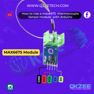
MAX6675 offers several advantages that make it popular among engineers and students. Its SPI interface ensures reliable digital communication with Arduino boards, while the cold-junction compensation improves measurement accuracy. The module provides ±2°C accuracy across its entire temperature range.
Additional features include a simple 5V power requirement, compact form factor, and direct thermocouple connection. These characteristics make the MAX6675 particularly suitable for educational projects, industrial applications, and DIY electronics where space and simplicity are important considerations.
The module:
To get started, you'll need several basic components. An Arduino Uno or Nano serves as the main controller, while the MAX6675 module handles temperature measurement. A K-type thermocouple probe is essential for actual temperature sensing.
You'll also need a breadboard and jumper wires for prototyping, and optionally a 16×2 LCD display for showing temperature readings without a computer. These components are readily available at electronics markets like Hall Road, Lahore, or from QKZEE Technologies.
| Component | Purpose | Price / link |
|---|---|---|
| Arduino Uno/Nano | Main controller | Arduino UNO R3 DIP — Rs 1,200 |
| MAX6675 Module | Thermocouple amplifier | Available on order — message us on WhatsApp |
| K-Type Thermocouple | Temperature sensor | Available on order — message us on WhatsApp |
| Breadboard & Jumper Wires | Circuit connections | Jumper wires Rs 180 + MB102 breadboard Rs 250 |
| 16×2 LCD (Optional) | Display temperature | LCD1602 with I2C module — Rs 660 |
| 5V Power Supply | Power Arduino & MAX6675 | 12V 2A adapter for the Arduino — Rs 275 (the MAX6675 itself runs on the Arduino's 5V) |
Proper wiring is crucial for the MAX6675 to function correctly. Connect the module's VCC pin to Arduino's 5V output and GND to ground. The SPI interface requires three connections: SCK to digital pin 13, CS to pin 10, and SO to pin 12.
The thermocouple wires should be inserted into the MAX6675's terminal block with correct polarity – typically red wire to positive and yellow/black to negative. If adding an LCD, connect it via I2C using Arduino's analog pins A4 (SDA) and A5 (SCL).
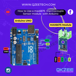
| MAX6675 Pin | Arduino Pin |
|---|---|
| VCC | 5V |
| GND | GND |
| SCK | D13 (SCK) |
| CS | D10 (SS) |
| SO | D12 (MISO) |
Programming the Arduino to read MAX6675 data is straightforward. First, install the MAX6675 library in the Arduino IDE. The code initializes the SPI communication and continuously reads temperature values in Celsius and Fahrenheit.
The example sketch provided demonstrates basic functionality, printing temperature readings to the serial monitor every second. You can easily modify this code to add features like LCD output, temperature logging, or control logic for your specific application.
Install the MAX6675 library (Adafruit or similar) via Arduino IDE.
#include "max6675.h"

// Define MAX6675 pins
int thermoDO = 12;  // SO
int thermoCS = 10;  // CS
int thermoCLK = 13; // SCK

MAX6675 thermocouple(thermoCLK, thermoCS, thermoDO);

void setup() {
  Serial.begin(9600);
  delay(500); // Stabilize MAX6675
}

void loop() {
  float tempC = thermocouple.readCelsius();
  float tempF = thermocouple.readFahrenheit();

  Serial.print("Temperature: ");
  Serial.print(tempC);
  Serial.print("°C | ");
  Serial.print(tempF);
  Serial.println("°F");

  delay(1000); // Update every second
}The old expected output did not match the code — fixed. The old output showed a line which the code never prints and two bare lines which the code never prints — it prints one line with both °C and °F separated by "|". The correct output for this code is:
Temperature: 25.00 °C | 77.00 °F
Temperature: 25.25 °C | 77.45 °F
(One line per second, °C and °F together. Your numbers will differ — they depend on the actual temperature at the thermocouple tip.)
After uploading the code, open the serial monitor to verify temperature readings. Common issues include incorrect wiring (especially SPI connections), poor thermocouple contact, or electrical interference. If readings appear unstable, check all connections and ensure the thermocouple is properly seated. The module may return 0°C if communication fails, indicating potential wiring problems or library issues. Proper grounding and avoiding nearby high-current devices can improve measurement stability.
| Problem | Solution |
|---|---|
| No reading (0.00°C) | Check wiring (SCK, CS, SO) |
| Incorrect temperature | Verify thermocouple polarity |
| Module overheating | Don't exceed 5V on VCC |
| Fluctuating values | Keep away from electrical noise |
The MAX6675 finds use in numerous real-world applications. Engineering students frequently incorporate it into final year projects like smart kilns or temperature-controlled systems. Industrial applications include furnace monitoring, food processing equipment, and HVAC systems. Hobbyists use it for 3D printer hotend monitoring, DIY reflow ovens, and scientific experiments. Its wide temperature range and digital output make it versatile for both educational and professional temperature measurement needs.
For a lower-temperature sensor that works the same way over I2C, see our 10k thermistor temperature sensor guide — it covers the thermistor version of this project.
The MAX6675 thermocouple module is perfect for high-temperature sensing with Arduino. Whether you're a student, engineer, or hobbyist, this guide helps integrate it into automation, FYPs, or industrial systems.
For a temperature-controlled safety system that switches things off when it gets too hot, see our IoT geyser safety system — it uses a temperature sensor with automatic cut-offs, the same pattern you can build with the MAX6675.
The Arduino UNO (Rs 1,200), 16×2 LCD with I2C (Rs 660), jumper wires (Rs 180), MB102 breadboard (Rs 250) and 12V 2A adapter (Rs 275) are available at QKZEE Technologies, Shop 20, 1st Floor, Al-Khalil Center, Hall Road, Lahore, and online at qkzeetech.com with delivery all over Pakistan — see the links above. The MAX6675 module and the K-type thermocouple are available on order — message us on WhatsApp and we will arrange them for you.
If the reading is 0°C, or the temperature jumps around, message us — tell us what the Serial Monitor shows, whether the thermocouple wires are red to + and black/yellow to −, and whether the module is powered from 5V, and we will help you find the fault.
Chat on WhatsApp Watch on YouTube
Why does the Serial Monitor show 0.00°C?
The module returns 0°C when SPI communication fails. Check the wiring: SCK to D13, CS to D10, SO to D12, VCC to 5V, GND to GND. A loose SO wire is the most common cause.
Why is my temperature wrong by a large amount?
Check the thermocouple polarity — red to + and black/yellow to − in the terminal block. A reversed thermocouple reads wrong (and can read negative). Also check that the thermocouple tip is actually touching what you want to measure.
Why do the readings fluctuate?
Keep the thermocouple wires away from motors, heaters and other high-current devices — electrical noise disturbs the tiny thermocouple voltage. Short, twisted wires help. Also make sure the thermocouple is firmly seated in the terminal block.
Can the MAX6675 measure below 0°C?
No — its range is 0°C to 1024°C. For below-zero measurements you need a different sensor (for example, a DS18B20, which reads −55°C to +125°C).
Do I need the LCD?
No — the Serial Monitor shows the readings. The LCD is only for showing the temperature without a computer connected. If you add one, wire it via I2C (SDA → A4, SCL → A5).
Can I use the MAX6675 with an ESP32?
Yes — the SPI pins differ (the ESP32's default SPI pins are different from the UNO's), so change thermoDO, thermoCS and thermoCLK in the code to match the ESP32 pins you wire to. The library works the same way.
A MAX6675 with an Arduino is one of the best first high-temperature projects: five wires, one library and a thermocouple. Remember the three things that trip everyone up — VCC is 5V (never more), the thermocouple polarity (red to +), and the SPI pins (SCK to D13, CS to D10, SO to D12). That is the whole project, and it works.