- +92-302-8577025
- qkzeetech@gmail.com
- shop 20, 1st floor Al-khalil Center Hall Road , Lahore
A breadboard is one of the most important tools for anyone learning electronics. It allows you to build and test electronic circuits without soldering — a reusable platform for DIY projects, Arduino projects and IoT systems. Learning how to use a breadboard is the first step toward becoming an electrical engineer or electronics hobbyist, and it is where every engineering project begins.
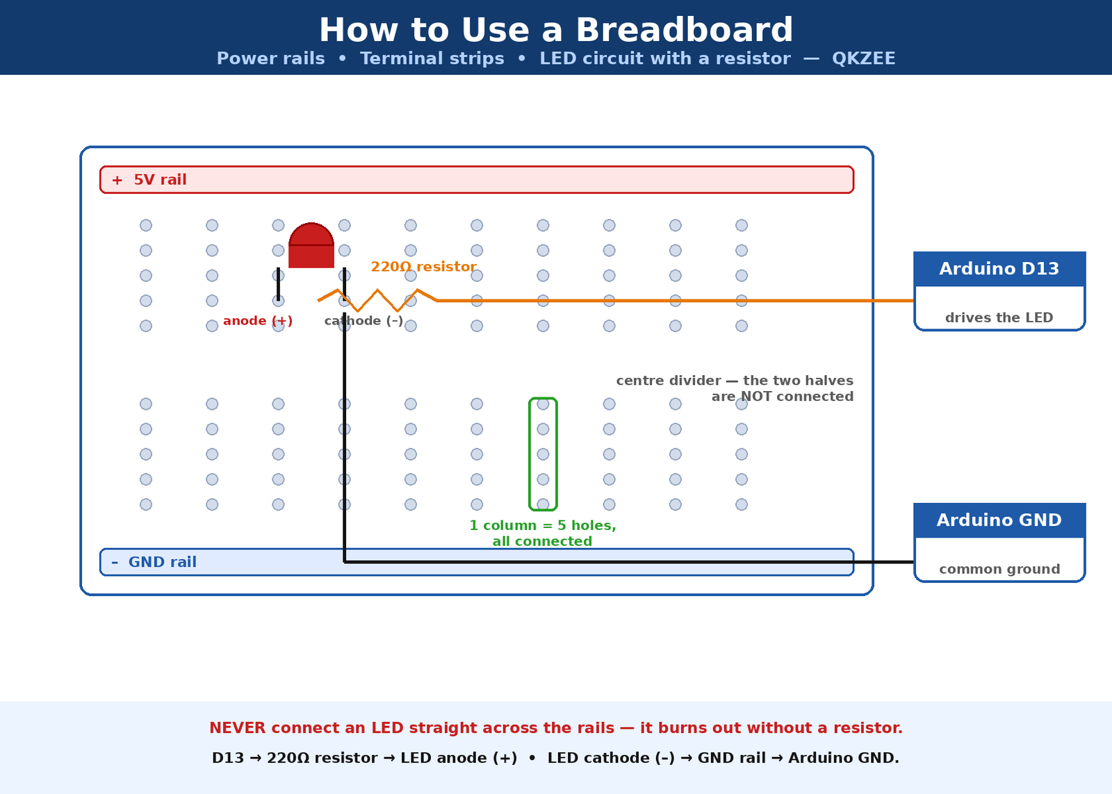
A breadboard (also called a solderless breadboard) is a plastic board full of holes with metal clips inside. You push component legs and jumper wires into the holes, and the clips connect them together — no soldering, no permanent connections. When a circuit works, you can pull everything out and build the next one on the same board. That is why students use it for every first circuit: it is fast, forgiving and cheap.
Understanding the breadboard layout helps you make accurate connections. A standard breadboard (like the MB102, 830 points) consists of:
When creating IoT, automation or Arduino-based projects, connect the 5V and GND pins of your Arduino board to the power rails. This supplies power to all components connected to the breadboard. On some larger boards the power rails are split in the middle — if a circuit on one side of the board gets no power, check the rail with a multimeter and bridge the gap with a jumper wire.
If you buy a breadboard, make sure it is of good quality — loose connections can cause project failures.
Learning how to make circuits on a breadboard is simple once you understand the placement rules.
Insert resistor legs into separate rows to limit current to components like LEDs or sensors. A resistor must always bridge two different rows — if both legs go into the same column of 5 holes, the resistor is shorted out and does nothing.
Never connect an LED straight across the power rails. The old version of this post said "Place the longer leg (anode) in the positive rail and the shorter leg (cathode) toward the ground" — with no resistor in that step, that is a direct rail-to-rail LED, which draws too much current and burns out. The correct way:
The resistor limits the current to about 15 mA. Without it, the LED takes as much current as the supply can give and burns out in seconds.
Insert the IC across the centre divider so each side sits on a separate set of rows. This ensures correct wiring to both sides. The notch or dot on the chip marks pin 1 — check the datasheet before you wire it, because a chip inserted backwards will not work and can be damaged.
These simple techniques are essential for school projects, university projects and engineering projects using Arduino, ESP32 or Raspberry Pi boards.
Beginners often make errors that stop circuits from working. Avoid these breadboard mistakes:
If your IoT project or DLD project doesn't work, double-check these issues. Even advanced industrial automation and CNC projects rely on accurate circuit placement.
Let's create your first breadboard project using an Arduino UNO. This will help you learn how to use a breadboard effectively.
| Component | Price / link |
|---|---|
| Arduino UNO R3 DIP | Arduino UNO R3 DIP ATmega328P with USB Cable — Rs 1,200 |
| MB102 breadboard (830 points) | MB102 Breadboard 830 Points — Rs 250 |
| 5mm LED | 5mm Diffused LED — Rs 6 |
| 220Ω resistor | No QKZEE listing — available at the Hall Road shop on request |
| Jumper wires | 40-Pin Jumper Wires 30cm — Rs 180 |

int ledPin = 13;

void setup() {
  pinMode(ledPin, OUTPUT);
}

void loop() {
  digitalWrite(ledPin, HIGH);
  delay(1000);
  digitalWrite(ledPin, LOW);
  delay(1000);
}
Upload the code, and your LED will blink every second. If you have never uploaded a sketch before, see our How to Upload Code in Arduino UNO guide — the upload steps are the same.
This small project helps students understand breadboard wiring and circuit prototyping — essential for final year projects in Pakistan.
Why do engineers and students love using breadboards?
Whether you are working on Raspberry Pi projects, Firebase projects, or ThingSpeak IoT systems, the breadboard saves time and money during experimentation. Our automatic night light switch is a good next project — it is built on the same MB102 breadboard.
Once your circuit works perfectly on a breadboard, it's time to design a PCB (Printed Circuit Board) for permanent installation. At QKZEE Technologies, Hall Road, Lahore, students receive consultation for final year projects and guidance on converting breadboard prototypes into professional PCBs — from DIY projects to industrial automation.
The Arduino UNO (Rs 1,200), MB102 breadboard (Rs 250), 5mm LED (Rs 6) and jumper wires (Rs 180) are available at QKZEE Technologies, Shop 20, 1st Floor, Al-Khalil Center, Hall Road, Lahore, and online at qkzeetech.com with delivery all over Pakistan — see the links above. The 220Ω resistor is available at the Hall Road shop on request.
If your LED does not blink, or nothing on the board gets power, message us — tell us which step you are on and what the LED does, and we will help you find the fault.
Why does my LED not light up?
Check three things: the resistor is in series (D13 → resistor → LED anode), the cathode goes to GND, and the LED is the right way round (long leg = anode). Also check that the resistor and the LED are in different rows — if both legs of a part sit in the same column of 5 holes, it is shorted out.
Why does my LED burn out?
It was connected without a resistor. An LED always needs a current-limiting resistor (220Ω is the standard for 5V). Never connect an LED straight across the power rails.
Why does only half my board work?
The two halves of the terminal strips are not connected across the centre divider — that is by design. And on some boards the power rails are split in the middle. Bridge the gap with a jumper wire.
Can I use a breadboard for a permanent project?
No — a breadboard is for testing. Once the circuit works, move it to a PCB or a soldered perfboard for permanent use.
Which breadboard should I buy?
The MB102 (830 points) is the standard for Arduino student projects — it fits an UNO, a few sensors and an IC comfortably. Smaller 400-point boards are fine for a single LED circuit.
Do I need to solder anything on a breadboard?
No. Everything pushes into the holes and the metal clips inside make the connections. That is the whole point of a breadboard.
A breadboard is the first tool every electronics student should master. Learn the layout — power rails, terminal strips, centre divider — always use a resistor with an LED, and test every circuit on the breadboard before you solder it. Once you can build the blinking LED circuit blindfolded, you are ready for any Arduino project.