- +92-302-8577025
- qkzeetech@gmail.com
- shop 20, 1st floor Al-khalil Center Hall Road , Lahore
In today's rapidly growing industries, industrial automation is the foundation of smart factories and modern production systems. From manufacturing plants in Pakistan to industrial setups, automation saves time, reduces errors and boosts efficiency.
One of the most exciting areas in engineering projects and final year projects is the integration of PLC (Programmable Logic Controllers) with Arduino. This combination delivers the reliability of PLC with the flexibility of Arduino IoT solutions, making it perfect for student projects, engineering universities, DIY automation enthusiasts and engineering service companies.
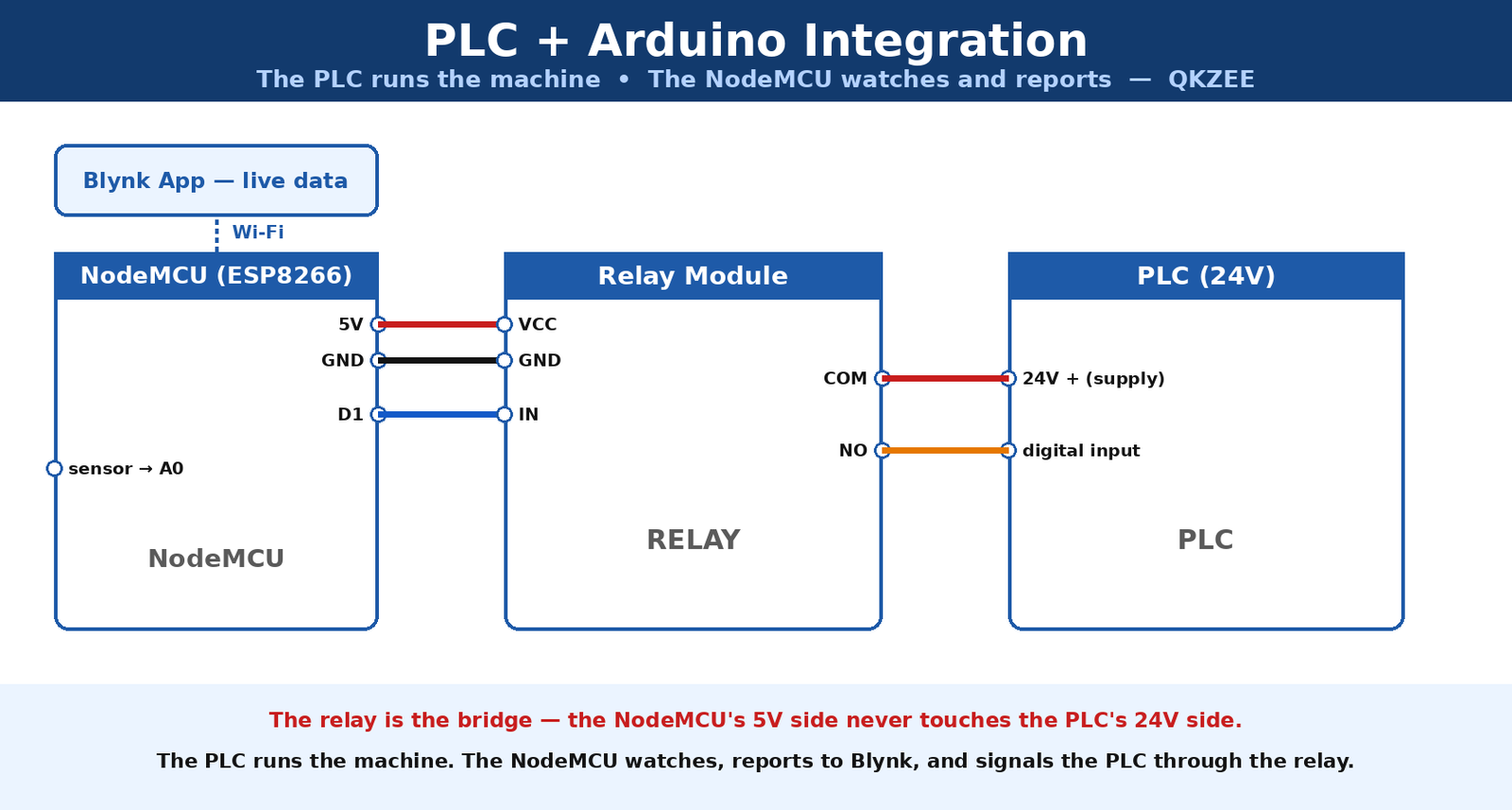
A PLC is built for factories: it runs for years without stopping, survives dust and heat, and switches motors and valves on a strict program. An Arduino (or NodeMCU) is built for flexibility: it reads sensors, connects to Wi-Fi and sends data to the cloud. Put together, the PLC runs the machine and the Arduino watches it — the PLC handles the critical automation, and the Arduino adds IoT monitoring, sensor data logging and cloud updates. That division of labour is the whole idea of this project, and it is why it works so well as a final year project for engineering students in Pakistan.
PLC systems are robust but expensive. By integrating Arduino, students and industries can handle non-critical or secondary tasks (like IoT monitoring, sensor data logging or cloud updates) while the PLC manages critical automation.
With Arduino, you can add IoT modules, Wi-Fi, sensors and smart features. Integration allows engineers to build DIY automation systems that meet unique industrial needs.
Perfect for student projects, semester projects and final year projects. Engineering students learn how to combine hardware (PLC) with open-source controllers (Arduino). This makes it an attractive project for engineering universities in Pakistan.
To implement PLC + Arduino integration, students require:
| Component | Price / link |
|---|---|
| PLC (Programmable Logic Controller) | Industrial part — not a QKZEE listing |
| Arduino UNO R3 DIP or ESP8266 NodeMCU | Rs 1,200 / Rs 590 |
| 1-channel relay module — the bridge between the two sides | Rs 155 |
| Sensors: DHT11 temperature & humidity, soil moisture, IR sensor | Rs 215 / Rs 155 / Rs 115 |
| Jumper wires + MB102 breadboard | Rs 180 / Rs 250 |
| HMI panels or Blynk IoT app | Blynk app is free on your phone |
Most of these components can be easily purchased from QKZEE Technologies, Hall Road, Lahore, or electronic shops in electronics markets.
This integration makes it a hybrid solution, combining industrial strength with modern IoT innovation.
The relay is the part that makes the integration safe. The NodeMCU runs on 5V (and its pins are 3.3V logic). The PLC runs on 24V. Those two sides must never touch — 24V would destroy the NodeMCU instantly. The relay sits between them: the NodeMCU drives the relay's coil (5V side), and the relay's contacts switch the PLC's 24V input circuit. When the NodeMCU sets D1 LOW, the relay clicks, COM connects to NO, and the PLC's digital input sees 24V. When the NodeMCU sets D1 HIGH, the relay opens and the input goes back to 0V. See our guide: How to Connect a Relay Module with Arduino — it explains COM, NO and NC and the active-LOW behaviour.
Below is a complete NodeMCU sketch that reads a sensor, sends the value to Blynk, and signals the PLC through the relay. This is a NodeMCU (ESP8266) sketch, not an UNO sketch — D1 and A0 are NodeMCU pins, and the Blynk library is the ESP8266 one. The old version of this post called it "Arduino code" and printed it as comma-joined fragments with curly quotes that would not compile.
#define BLYNK_TEMPLATE_ID "Your_Template_ID"
#define BLYNK_AUTH_TOKEN "Your_Blynk_Token"

#include <ESP8266WiFi.h>
#include <BlynkSimpleEsp8266.h>

char auth[] = BLYNK_AUTH_TOKEN;
char ssid[] = "Your_WiFi_SSID";
char pass[] = "Your_WiFi_Password";

int sensorPin = A0;
int relayPin = D1;
int sensorValue = 0;
int threshold = 400;

void setup() {
  Serial.begin(115200);
  Blynk.begin(auth, ssid, pass);
  pinMode(relayPin, OUTPUT);
  digitalWrite(relayPin, HIGH);   // relay OFF (most modules are active LOW)
}

void loop() {
  Blynk.run();
  sensorValue = analogRead(sensorPin);
  Blynk.virtualWrite(V1, sensorValue);

  if (sensorValue < threshold) {
    digitalWrite(relayPin, LOW);    // relay ON — signals the PLC input
    Blynk.virtualWrite(V2, 1);
  } else {
    digitalWrite(relayPin, HIGH);   // relay OFF — PLC input back to 0V
    Blynk.virtualWrite(V2, 0);
  }
}
This code lets the NodeMCU send sensor data to Blynk IoT while interacting with PLC inputs and outputs. Replace "Your_Template_ID", "Your_Blynk_Token", "Your_WiFi_SSID" and "Your_WiFi_Password" with your own Blynk project values before uploading. The relay's contacts go to the PLC's 24V input circuit — never to the NodeMCU's pins.
See our Top 10 Final Year Project Ideas — PLC + Arduino is idea #3 on the list.
The future lies in:
Engineering universities in Pakistan will increasingly adopt PLC Arduino integration projects in final year curricula.
The integration of PLC and Arduino is shaping the future of industrial automation in Pakistan, India and beyond. It provides reliability, flexibility and cost-effectiveness — making it one of the best final year projects and engineering projects for students. From QKZee Technologies, Hall Road, Lahore, to engineering universities, students and service providers are adopting this IoT-based automation project.
Looking for affordable components for this Arduino project? Check out QKZEE Technologies, an online shop in Lahore, Pakistan, offering the best components for students and DIY projects. Whether you are looking for sensors, modules or other electronics at a good price, they have it all — see the links in the components table above, or visit qkzeetech.com.
If you are stuck on the PLC side, the relay wiring or the Blynk setup, message us — tell us which side you are on and what the relay does when you upload the code, and we will help you find the fault.
Chat on WhatsApp Watch on YouTube
What is the difference between a PLC and an Arduino?
A PLC is an industrial controller built to run machines reliably for years in harsh conditions. An Arduino (or NodeMCU) is a flexible open-source board for sensors, Wi-Fi and IoT. This project uses the PLC for the machine and the Arduino for the monitoring.
Why do I need a relay between the PLC and the Arduino?
The two sides run at different voltages — the NodeMCU at 5V (3.3V logic) and the PLC at 24V. The relay's contacts isolate them: the NodeMCU drives the coil, and the contacts switch the PLC's 24V input. Without it, 24V would destroy the NodeMCU.
Can I use an Arduino UNO instead of a NodeMCU?
Yes, for the relay part — but the UNO has no Wi-Fi, so you lose the Blynk monitoring unless you add a Wi-Fi module. The NodeMCU has Wi-Fi built in, which is why the code above uses it.
What is Blynk?
Blynk is a free phone app that shows live sensor data and lets you control the project from your phone. You create a project in the app, and it gives you a template ID and an auth token — those are the placeholders in the code.
Is this project suitable for a final year project?
Yes — it combines industrial automation (PLC) with IoT (NodeMCU + Blynk), which is exactly what examiners look for. It is idea #3 in our Top 10 Final Year Project Ideas.
What if I do not have a PLC?
Build the NodeMCU + relay + sensor half first and demonstrate it with a 12V bulb as the load — that is the same circuit, and it proves the integration works. Add the PLC when your university lab gives you access to one.
A PLC and an Arduino do different jobs, and that is why they work so well together. Let the PLC run the machine, let the NodeMCU watch it and report to Blynk, and let a relay keep their voltages apart. Build the NodeMCU half first, test it with a bulb, then connect the PLC — and you have a final year project that shows both industrial and IoT skills.