- +92-302-8577025
- qkzeetech@gmail.com
- shop 20, 1st floor Al-khalil Center Hall Road , Lahore
Are you working on student projects, engineering projects, or industrial automation? The TCS3200 color sensor is a powerful and versatile tool that can elevate your projects to the next level. Whether you're a student in Lahore, an engineer in Pakistan, or a hobbyist exploring components on Hall Road, this blog will guide you through everything you need to know about the TCS3200 color sensor. At QKZee Technologies, we provide top-notch services and consultation to help you succeed in your projects.
The TCS3200 is a programmable color sensor that detects the red, green, and blue (RGB) components of light reflected from an object. It converts this information into a frequency signal that can be read by a microcontroller, such as an Arduino. This makes it an ideal choice for school projects, final year projects, and professional applications in automation and robotics.
Inside the sensor is an 8×8 array of photodiodes: 16 with a red filter, 16 with a green filter, 16 with a blue filter, and 16 with no filter (clear). Two pins (S2 and S3) choose which filter is active, and the OUT pin gives a square wave whose frequency depends on how much of that colour the sensor sees. The Arduino measures that frequency with pulseIn() — and from the three frequencies, it works out the colour.
For the full sensor comparison, see our best Arduino sensors guide.
To connect the TCS3200 color sensor to an Arduino, follow these steps:
| TCS3200 Pin | Arduino Pin |
|---|---|
| VCC | 5V |
| GND | GND |
| S0 | D8 |
| S1 | D9 |
| S2 | D10 |
| S3 | D11 |
| OUT | D12 |
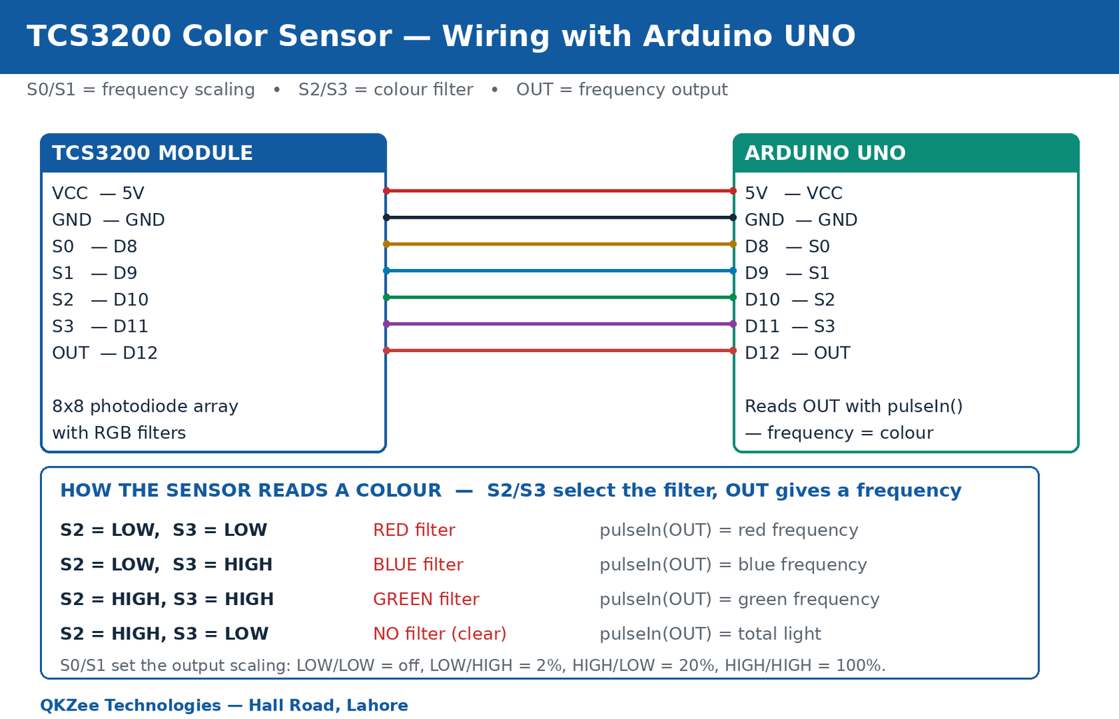
pulseIn() to measure reliably.Here's a simple Arduino code to read and interpret colors using the TCS3200 sensor:
// TCS3200 colour sensor — read R, G, B with pulseIn()
// S0 = D8, S1 = D9 (scaling), S2 = D10, S3 = D11 (filter), OUT = D12

const int S0 = 8;
const int S1 = 9;
const int S2 = 10;
const int S3 = 11;
const int OUT = 12;

void setup() {
  Serial.begin(9600);
  pinMode(S0, OUTPUT);
  pinMode(S1, OUTPUT);
  pinMode(S2, OUTPUT);
  pinMode(S3, OUTPUT);
  pinMode(OUT, INPUT);

  // Frequency scaling: 20% (S0 HIGH, S1 LOW)
  digitalWrite(S0, HIGH);
  digitalWrite(S1, LOW);
}

int readColour(int s2, int s3) {
  digitalWrite(S2, s2);
  digitalWrite(S3, s3);
  delay(100);  // let the sensor settle on the new filter
  return pulseIn(OUT, LOW);
}

void loop() {
  int red   = readColour(LOW, LOW);    // red filter
  int blue  = readColour(LOW, HIGH);   // blue filter
  int green = readColour(HIGH, HIGH);  // green filter

  Serial.print("R: ");
  Serial.print(red);
  Serial.print("  G: ");
  Serial.print(green);
  Serial.print("  B: ");
  Serial.println(blue);

  // The LOWEST frequency means the STRONGEST colour
  // (more light of that colour = higher frequency = shorter pulse)
  if (red < green && red < blue) {
    Serial.println("Detected: RED");
  } else if (green < red && green < blue) {
    Serial.println("Detected: GREEN");
  } else if (blue < red && blue < green) {
    Serial.println("Detected: BLUE");
  } else {
    Serial.println("Detected: unclear — check the light");
  }

  delay(500);
}
How to read the numbers: pulseIn() measures the length of one LOW pulse in microseconds. More light of a colour means a higher frequency, which means a SHORTER pulse — so the smallest number is the strongest colour. A red card gives the smallest number on the red filter; a green card gives the smallest on the green filter. If all three numbers are nearly equal, the sensor is seeing white, grey, or no clear colour — check the lighting (see FAQ Q1).
The full build costs Rs 3,455. To display the detected colour on an LCD, see our LCD & keypad projects guide.
If all three readings look the same, the sensor gives nonsense numbers, or the detected colour is always wrong, message us on WhatsApp and we'll help you debug it — or watch the build on our YouTube channel.
Chat on WhatsApp Watch on YouTube
Q1: Why do all three readings look the same?
Almost always the light. The sensor reads reflected light, so it needs bright, even, white light on the object — a desk lamp right above it works. In a dim room, or under yellow room lighting, all three filters see nearly the same thing. Also check that the sensor is close to the object (2–5 cm) and that S2/S3 are actually changing — a loose wire on D10 or D11 leaves the filter stuck on one colour.
Q2: Why does the sensor need light? Can't it work in the dark?
No. The TCS3200 does not emit light — it only measures the light bouncing off the object. In the dark there is nothing to measure. Some TCS3200 modules have built-in white LEDs on the board; if yours does, turn them on (they are usually wired to VCC already). If yours has no LEDs, add a bright white LED or a desk lamp above the object.
Q3: What is the difference between the TCS3200 and the TCS230?
Almost nothing — the TCS230 is the older version of the same chip, and the TCS3200 replaced it. They share the same pinout, the same S0/S1/S2/S3 logic and the same code. If a tutorial says TCS230, the wiring and sketch in this guide work exactly the same. Our shop listing covers both names.
Q4: Can the TCS3200 read any colour?
It reads red, green and blue separately, so it can tell apart clearly different colours (red, green, blue, yellow, white, black). It cannot give you an exact colour name or a hex code — the numbers depend on the light, the distance and the surface. For a sorting machine, calibrate it: hold each colour in front of the sensor, note the three numbers, and use those ranges in your code instead of guessing.
Q5: Why do the values jump around?
The sensor is sensitive to flickering light (tube lights flicker at 50 Hz) and to movement. Fix it by taking 5 readings of each colour and using the average, by keeping the sensor and the object still while reading, and by shielding the sensor from room light with a small tube or box around it. Also make sure the 20% scaling is set (S0 HIGH, S1 LOW) — at 100% the frequency can be too fast for pulseIn() to measure steadily.