- +92-302-8577025
- qkzeetech@gmail.com
- shop 20, 1st floor Al-khalil Center Hall Road , Lahore
The IR Obstacle Detection Sensor Module is a compact and versatile tool for hobbyists and roboticists in Lahore, Pakistan. It utilizes infrared technology to detect obstacles within its adjustable range. The sensor transmits infrared light, and any reflected light indicates an object in its path. This non-contact sensing makes it ideal for various line-following and obstacle-avoidance robot applications.
The TCRT5000 is a reflective optical sensor: an infrared LED and a phototransistor side by side in one small package. The LED shines infrared light down, and the phototransistor measures how much of it bounces back. A white surface reflects most of the light; a black surface absorbs it. That one difference is the whole trick behind a line-following robot: the sensor can tell whether it is over the white track or over the black line.
TCRT5000 vs the IR obstacle module: the old post mixed these two up. The TCRT5000 is a short-range reflective sensor (it works a few millimetres above the surface) and is used for line following. The IR obstacle-avoidance module (the 3-pin module with a 2–30 cm range) is a different sensor, used for detecting objects in front of a robot. Both are IR sensors, but they do different jobs — this guide is about the TCRT5000.
A line-following robot drives over a track — usually a black line on a white surface — with two TCRT5000 sensors mounted underneath, a few millimetres above the ground, one on the left and one on the right. The logic is simple:
| Left sensor | Right sensor | What it means | Robot does |
|---|---|---|---|
| White (HIGH) | White (HIGH) | On the track, centred | Drive forward |
| Black (LOW) | White (HIGH) | Drifting right, line is on the left | Turn left |
| White (HIGH) | Black (LOW) | Drifting left, line is on the right | Turn right |
| Black (LOW) | Black (LOW) | On the line (or at a crossing) | Stop or drive forward slowly |
The module's output is digital: HIGH over a white surface (light reflected) and LOW over a black line (light absorbed). If your robot does the opposite of what the table says, your module's logic is inverted — just swap the HIGH and LOW checks in the code.
While the basic principle remains the same, IR obstacle detection modules can come with additional features like:
| TCRT5000 module pin | Arduino |
|---|---|
| VCC | 5V |
| GND | GND |
| OUT | Digital pin (D2 for the left sensor, D3 for the right sensor) |
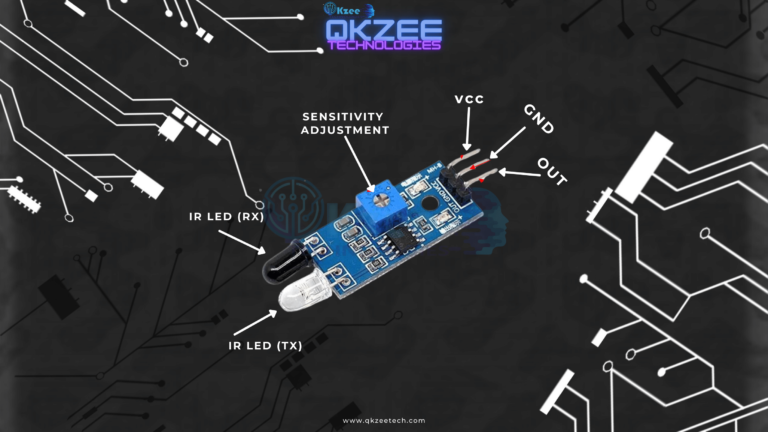
Mount the sensors 2–5 mm above the track — too high and they cannot tell black from white; too low and they scrape the ground. The onboard potentiometer sets the threshold: turn it until the output LED changes exactly as the sensor moves from white to black, then leave it alone.
| Component | Purpose | Price / link |
|---|---|---|
| TCRT5000 line tracking sensor | Line detection (×2 for a line follower) | Rs 130 each |
| IR sensor module | Obstacle detection (the 2–30 cm module) | Rs 115 |
| Arduino Uno | Main controller | Arduino UNO R3 DIP — Rs 1,200 |
| L298N motor driver | Drives the two motors | Rs 375 |
| DC gear motor | Wheels (×2) | Rs 165 each |
| 2WD robot car chassis | Chassis + motors + caster | Rs 920 |
| Jumper wires | Connections | Rs 180 |
| Breadboard | Prototyping | MB102 — Rs 250 |
// Line-following robot with two TCRT5000 sensors and an L298N motor driver
const int leftSensor  = 2;   // Left TCRT5000 OUT
const int rightSensor = 3;   // Right TCRT5000 OUT

// L298N motor driver pins
const int in1 = 8;   // Left motor direction
const int in2 = 9;   // Left motor direction
const int in3 = 10;  // Right motor direction
const int in4 = 11;  // Right motor direction
const int ena = 5;   // Left motor speed (PWM)
const int enb = 6;   // Right motor speed (PWM)

const int speed = 150;  // 0-255

void setup() {
  pinMode(leftSensor, INPUT);
  pinMode(rightSensor, INPUT);

  pinMode(in1, OUTPUT);
  pinMode(in2, OUTPUT);
  pinMode(in3, OUTPUT);
  pinMode(in4, OUTPUT);
  pinMode(ena, OUTPUT);
  pinMode(enb, OUTPUT);
}

void loop() {
  int left  = digitalRead(leftSensor);   // HIGH = white, LOW = black line
  int right = digitalRead(rightSensor);

  if (left == HIGH && right == HIGH) {
    // On the track, centred — drive forward
    forward();
  } else if (left == LOW && right == HIGH) {
    // Line is on the left — turn left
    turnLeft();
  } else if (left == HIGH && right == LOW) {
    // Line is on the right — turn right
    turnRight();
  } else {
    // Both on black — stop (or at a crossing)
    stopMotors();
  }
}

void forward() {
  digitalWrite(in1, HIGH); digitalWrite(in2, LOW);
  digitalWrite(in3, HIGH); digitalWrite(in4, LOW);
  analogWrite(ena, speed); analogWrite(enb, speed);
}

void turnLeft() {
  digitalWrite(in1, LOW);  digitalWrite(in2, HIGH);
  digitalWrite(in3, HIGH); digitalWrite(in4, LOW);
  analogWrite(ena, speed); analogWrite(enb, speed);
}

void turnRight() {
  digitalWrite(in1, HIGH); digitalWrite(in2, LOW);
  digitalWrite(in3, LOW);  digitalWrite(in4, HIGH);
  analogWrite(ena, speed); analogWrite(enb, speed);
}

void stopMotors() {
  digitalWrite(in1, LOW); digitalWrite(in2, LOW);
  digitalWrite(in3, LOW); digitalWrite(in4, LOW);
}
The two sensors read HIGH on white and LOW on black. When both read HIGH the robot is centred on the track and drives forward. When one sensor goes LOW it means the robot has drifted and the line is on that side, so the robot turns toward it. When both read LOW the robot is on the line (or at a crossing) and stops. The L298N drives the two motors: IN1/IN2 control the left motor, IN3/IN4 control the right motor, and ENA/ENB (PWM pins 5 and 6) set the speed.
For a complete robot car that uses a motor driver and an ultrasonic sensor, see our obstacle-avoidance robot car guide — it uses the same L298N wiring with an HC-SR04 instead of line sensors.
The same module also works as a short-range obstacle detector: mount it facing forward, a few millimetres from the surface it should watch. When an object comes within range, the reflected IR changes the output and the Arduino can stop or turn the robot. For longer-range obstacle detection (2–30 cm), use the IR obstacle-avoidance module instead — it is designed for that job, while the TCRT5000 is designed for line following.
Head to the bustling halls of electronic shops in Hall Road, Lahore, or explore online stores like QKZee Technologies to find the perfect IR sensor or IR obstacle detection module for your project. Consider factors like:
By following these guidelines, you'll be well on your way to incorporating this powerful sensor into your next robotic creation in Lahore, Pakistan!
The TCRT5000 line tracking sensor (Rs 130 each), IR sensor module (Rs 115), Arduino UNO R3 DIP (Rs 1,200), L298N motor driver (Rs 375), DC gear motor (Rs 165 each), 2WD robot car chassis kit (Rs 920), jumper wires (Rs 180) and MB102 breadboard (Rs 250) are available at QKZEE Technologies, Shop 20, 1st Floor, Al-Khalil Center, Hall Road, Lahore, and online at qkzeetech.com with delivery all over Pakistan — see the links above.
If the robot spins in circles, or ignores the line completely, message us — tell us whether the sensors are 2–5 mm above the track, whether the output LED changes when you move a sensor from white to black, and which pins the sensors are on, and we will help you find the fault.
What is the difference between the TCRT5000 and the IR obstacle module?
The TCRT5000 is a short-range reflective sensor (a few millimetres) used for line following — it tells black from white. The IR obstacle module detects objects 2–30 cm away and is used for obstacle avoidance. They look similar but do different jobs.
Why does my robot spin in circles?
The sensors are probably reading the wrong way round — check whether the output LED changes when you move a sensor from white to black. If the robot turns the wrong way, swap the HIGH and LOW checks in the code.
How high should the sensors be above the track?
2–5 mm. Too high and they cannot tell black from white; too low and they scrape the ground.
Why does the robot work on white paper but not on my track?
The track's black line may not be dark enough, or the surface may be glossy and reflect IR even where it is black. Use a matte black tape or marker on white paper, and calibrate the potentiometer on the module.
Can I use one TCRT5000 instead of two?
Yes for a simple follower, but it can only tell you whether it is on the line or off it — it cannot tell which way to turn. Two sensors (left and right) are the standard setup.
Can I use the TCRT5000 with an ESP32?
Yes — the module works on 3.3V or 5V. On the ESP32, connect OUT to any digital pin and use the same logic (HIGH = white, LOW = black).
The TCRT5000 is the sensor that makes line-following robots possible: two modules, a few millimetres above a black line, and a simple HIGH/LOW rule that tells the robot where to turn. Keep the sensors low, calibrate the potentiometer, and remember that the TCRT5000 is for line following while the IR obstacle module is for obstacle detection. For another project that uses an IR sensor, see our automatic tap water system guide — it uses the IR obstacle module to detect a hand under the tap.