- +92-302-8577025
- qkzeetech@gmail.com
- shop 20, 1st floor Al-khalil Center Hall Road , Lahore
A smart helmet with accident detection is a safety project that watches the rider's motion, detects a crash, and sends an SMS with the location to an emergency contact. It is a popular choice for school and university students in Pakistan who want a final year project that combines sensors, Arduino, GSM and GPS in one working system.
This guide builds the full system: an MPU6050 accelerometer watches for a sudden impact, a vibration sensor confirms the crash, the Arduino reads the GPS coordinates, and a SIM800L GSM module sends an SMS with a Google Maps link. The HC-05 Bluetooth module is optional and is not needed for the alert to work.
This is a student demonstration model, not a certified safety device. Always wear a proper certified helmet on the road - this project shows how the detection and alert system works, it does not make an ordinary helmet crash-proof.
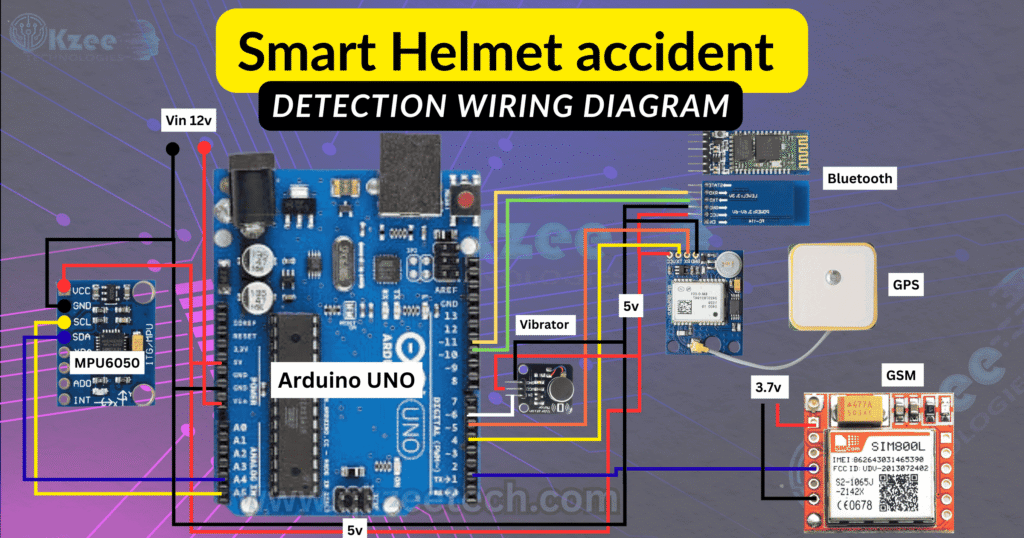
The helmet uses five parts that each do one job:
When a crash is detected, the Arduino waits 10 seconds, reads the GPS position, and sends one SMS: "Accident detected! Rider may need help" plus a Google Maps link. The SMS needs a SIM card with balance and mobile network coverage, and the GPS needs a clear view of the sky to get a fix.
| Component | Price / link |
|---|---|
| Arduino UNO R3 DIP | Arduino UNO R3 DIP ATmega328P with USB Cable - Rs 1,200 |
| Arduino Nano V3 (smaller, better fit inside a helmet) | Arduino Nano V3 ATmega328P with USB Cable - Rs 650 (without cable) / Rs 750 (with cable) |
| MPU6050 accelerometer + gyroscope module | No QKZEE listing - available at the Hall Road shop on request |
| SW-420 vibration sensor module | No QKZEE listing - available at the Hall Road shop on request |
| SIM800L GSM module | No QKZEE listing - available at the Hall Road shop on request |
| NEO-6M GPS module with antenna | No QKZEE listing - available at the Hall Road shop on request |
| HC-05 Bluetooth module (optional) | No QKZEE listing - available at the Hall Road shop on request |
| 18650 Li-ion cell 2000mAh | 18650 Lithium-Ion Rechargeable Cell 2000mAh - Lot Rs 200 / New Rs 250 |
| Single cell 18650 battery holder | Single Cell 18650 Battery Holder - Rs 45 |
| MB102 breadboard (for testing on the bench) | MB102 Breadboard 830 Points - Rs 250 |
| 40-pin jumper wires | 40-Pin Jumper Wires 30cm - Rs 180 |
| A helmet, foam padding, a SIM card with balance | From a local shop |
Use the UNO on the bench and the Nano for the final helmet build - the Nano is much smaller and the code and wiring are the same. Do not drill through the helmet shell or cut its protective foam to fit the electronics; mount the modules on the inner padding with foam and cable ties.
Wire the modules to the Arduino as follows. The MPU6050 uses the I2C pins (A4 and A5 on the UNO and Nano). The three serial modules share SoftwareSerial - the Arduino UNO has only one hardware serial port, which is used for the USB connection to the computer, so the sketch switches between the GPS and GSM modules with .listen().
| MPU6050 pin | Arduino pin |
|---|---|
| VCC | 5V |
| GND | GND |
| SDA | A4 |
| SCL | A5 |
| Vibration sensor pin | Arduino pin |
|---|---|
| VCC | 5V |
| GND | GND |
| DO (digital output) | D3 |
| SIM800L pin | Arduino pin |
|---|---|
| TX | D7 |
| RX | D8 |
| VCC | 3.7-4.2V from a separate source (a Li-ion cell or a buck converter that can give 2A) |
| GND | GND (common ground with the Arduino) |
Do not power the SIM800L from the Arduino 5V pin. The module draws up to 2A in short bursts when it sends an SMS, which the Arduino regulator cannot supply - the board will reset or the regulator can be damaged.
| GPS pin | Arduino pin |
|---|---|
| TX | D4 |
| RX | D5 |
| VCC | 5V |
| GND | GND |
| HC-05 pin | Arduino pin |
|---|---|
| TX | D10 |
| RX | D11 (through a 1k + 2k voltage divider - the HC-05 RX pin is 3.3V logic) |
| VCC | 5V |
| GND | GND |
Power the Arduino from a 5V power bank through the USB port, or feed 7-12V into the VIN pin (the wiring diagram shows a 12V feed into VIN). The SIM800L always needs its own 3.7V source as shown above - it is the only module that must not share the Arduino supply.
Install these from the Arduino IDE Library Manager (Sketch - Include Library - Manage Libraries):
SoftwareSerial and Wire are built into the Arduino IDE - no install needed.
/*
  Smart Helmet with Accident Detection
  Board: Arduino UNO (or Nano - same pins, same code).
  MPU6050 (I2C) + SW-420 vibration sensor detect a crash,
  NEO-6M GPS gives the location, SIM800L sends an SMS with a
  Google Maps link. The HC-05 Bluetooth module is optional
  and is NOT used by this sketch.
*/

#include <Wire.h>
#include <Adafruit_MPU6050.h>
#include <Adafruit_Sensor.h>
#include <SoftwareSerial.h>
#include <TinyGPS++.h>
#include <math.h>

Adafruit_MPU6050 mpu;
TinyGPSPlus gps;

SoftwareSerial gsmSerial(7, 8);   // SIM800L: TX -> D7, RX -> D8
SoftwareSerial gpsSerial(4, 5);   // NEO-6M: TX -> D4, RX -> D5

const int vibPin = 3;              // SW-420 digital output -> D3

// <-- APNA EMERGENCY NUMBER YAHAN LIKHAIN (country code ke saath) -->
const char* EMERGENCY_NUMBER = "+92XXXXXXXXXX";

// At rest the acceleration is about 9.8 m/s^2 (gravity).
// A crash spikes above 25 m/s^2 (about 2.5 g); a free fall drops below 2.
const float CRASH_HIGH = 25.0;
const float CRASH_LOW  = 2.0;
const unsigned long COOLDOWN_MS = 60000;  // 60 seconds between alerts

unsigned long lastAlert = 0;

void setup() {
  Serial.begin(9600);
  gsmSerial.begin(9600);
  gpsSerial.begin(9600);

  pinMode(vibPin, INPUT);

  if (!mpu.begin()) {
    Serial.println("MPU6050 not found! Check SDA -> A4, SCL -> A5.");
    while (1) { delay(10); }
  }
  mpu.setAccelerometerRange(MPU6050_RANGE_8_G);

  Serial.println("Smart Helmet ready.");
  Serial.println("Shake the helmet hard to test, or wait for a real impact.");
}

void loop() {
  sensors_event_t a, g, temp;
  mpu.getEvent(&a, &g, &temp);

  float mag = sqrt(a.acceleration.x * a.acceleration.x
                 + a.acceleration.y * a.acceleration.y
                 + a.acceleration.z * a.acceleration.z);
  int vibration = digitalRead(vibPin);

  // Keep the GPS parser fed while we monitor
  gpsSerial.listen();
  while (gpsSerial.available()) {
    gps.encode(gpsSerial.read());
  }

  bool crash = (mag > CRASH_HIGH || mag < CRASH_LOW) && (vibration == HIGH);

  if (crash && (millis() - lastAlert > COOLDOWN_MS)) {
    lastAlert = millis();
    sendAlertSMS();
    delay(5000);
  }

  delay(100);
}

void sendAlertSMS() {
  Serial.println("Crash suspected! Reading GPS, then sending SMS in 10 seconds...");
  delay(10000);

  // Give the GPS up to 8 seconds to deliver a fresh fix
  gpsSerial.listen();
  unsigned long start = millis();
  while (millis() - start < 8000) {
    while (gpsSerial.available()) {
      gps.encode(gpsSerial.read());
    }
    if (gps.location.isUpdated()) break;
  }

  String message = "Accident detected! Rider may need help. ";
  if (gps.location.isValid()) {
    message += "Location: https://maps.google.com/?q=";
    message += String(gps.location.lat(), 6);
    message += ",";
    message += String(gps.location.lng(), 6);
  } else {
    message += "GPS fix not available yet. Check the rider's last known location.";
  }

  gsmSerial.listen();
  gsmSerial.println("AT+CMGF=1");
  delay(500);
  gsmSerial.print("AT+CMGS=\"");
  gsmSerial.print(EMERGENCY_NUMBER);
  gsmSerial.println("\"");
  delay(500);
  gsmSerial.print(message);
  gsmSerial.write(26);  // Ctrl+Z sends the SMS
  delay(2000);

  Serial.println("SMS sent:");
  Serial.println(message);
}
The 10-second wait is a pause before the SMS goes out. This simple build has no cancel button - adding a push button that cancels the alert inside those 10 seconds is a good extension for your own version.
Wire everything on the breadboard and upload the sketch before putting anything in a helmet. Open the Serial Monitor at 9600 baud and check that it prints "Smart Helmet ready."
Fix the MPU6050 and the vibration sensor firmly inside the helmet on the inner padding, with the MPU6050 flat. A loose sensor rattles and gives false readings.
Place the SIM800L, GPS and Arduino in foam casing so nothing shorts against the helmet shell. Keep the GPS antenna facing up and the SIM800L antenna clear of metal.
Replace the breadboard jumper wires with soldered connections for the final build - loose jumpers fall out inside a helmet. Keep the SIM800L on its own 3.7V supply as wired above.
Put your real emergency number in EMERGENCY_NUMBER at the top of the sketch, then upload with the Arduino IDE.
Shake the helmet hard while it sits on a table and check that the SMS arrives with a Maps link. Do not wear the helmet during the crash test - test it on a cushion, not on your head.
CRASH_HIGH from 25 to 30, or mount the vibration sensor more firmly so it only triggers on a real shock.The Arduino UNO, Nano, jumper wires, breadboard, 18650 cell and holder are available at QKZEE Technologies, Shop 20, 1st Floor, Al-Khalil Center, Hall Road, Lahore, and online at qkzeetech.com with delivery all over Pakistan - see the links above. The MPU6050, vibration sensor, SIM800L, NEO-6M GPS and HC-05 modules are available at the Hall Road shop on request.
If the SMS does not arrive, or the GPS never gets a fix, message us - tell us what the Serial Monitor shows and which step you are on, and we will help you find the fault.
Chat on WhatsAppWatch on YouTube
Can I use an Arduino Nano instead of the UNO?
Yes. The Nano is smaller and fits inside a helmet much better. The pins are the same (A4/A5, D3, D4/D5, D7/D8) and the code is identical.
Does the SMS really include the location?
Yes - when the GPS has a fix, the SMS contains a Google Maps link with the latitude and longitude. If there is no fix yet, the SMS says so honestly instead of sending a wrong location.
Why does the GPS take minutes the first time?
That is a cold start: the GPS module has to download satellite data first. It needs a clear view of the sky and can take 2-5 minutes. Later fixes are much faster.
Can the SIM800L run from the Arduino 5V pin?
No. It draws up to 2A in short bursts when sending an SMS. Use a separate 3.7V Li-ion cell or a buck converter that can give 2A, with a common ground to the Arduino.
Will it work without the HC-05 Bluetooth module?
Yes. The Bluetooth module is optional and the sketch does not use it. It is only useful if you want to add a mobile app later.
Is this a real safety device I can rely on in a crash?
No. This is a student demonstration model for learning and for final year project demos. It can miss a crash and it can send a false alarm. Always wear a proper certified helmet on the road.
Building a smart helmet with accident detection brings together motion sensing, vibration confirmation, GPS location and GSM alerts in one project. Follow the wiring above, put your real emergency number in the sketch, and test the SMS on the bench before the helmet goes anywhere near the road. With the code in this guide, students in Pakistan can build and demonstrate a working system and explain every part of it to their teachers and judges.