- +92-302-8577025
- qkzeetech@gmail.com
- shop 20, 1st floor Al-khalil Center Hall Road , Lahore
An ESP8266 smart classroom attendance system uses Wi-Fi to automate student attendance. Each student taps an RFID card on the reader, the NodeMCU reads the card's ID, and the record goes straight to a Firebase cloud database with the real date and time — no registers, no manual counting. Teachers can check attendance from a mobile or PC.
It is a student and final year project — a working system you can demonstrate in a real classroom with a few cards.
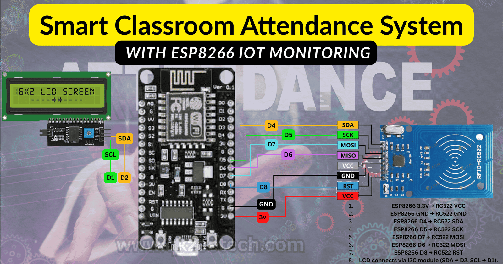
/Attendance/<card UID>/.0x27)| RC522 Pin | NodeMCU Pin |
|---|---|
| VCC | 3.3V (not 5V — the RC522 is a 3.3V module) |
| GND | GND |
| SDA (SS) | D4 |
| SCK | D5 |
| MOSI | D7 |
| MISO | D6 |
| RST | D8 |
| LCD Pin | NodeMCU Pin |
|---|---|
| SDA | D2 |
| SCL | D1 |
| VCC / GND | 5V / GND |
| Component | Price / link |
|---|---|
| ESP8266 NodeMCU | NodeMCU ESP8266 CH340 WiFi Board — Rs 590 |
| 40-Pin Jumper Wires 30cm | 40-Pin Jumper Wires 30cm — Rs 180 |
| MB102 Breadboard | MB102 Breadboard 830 Points — Rs 250 |
The RC522 RFID reader, RFID cards/tags, 16×2 LCD and 5V power source do not have individual listings in the QKZEE shop — they are available at the Hall Road shop on request.
classroom-attendance) and continue. Google Analytics is optional — you can skip it.https://classroom-attendance-default-rtdb.firebaseio.com.</>), register the app, and copy the Web API Key (apiKey).Install these from the Arduino IDE Library Manager (Sketch → Include Library → Manage Libraries):
Firebase_ESP_Client.h)/*
ESP8266 Smart Classroom Attendance System
Board: NodeMCU ESP8266 (ESP-12E).
RC522 RFID reader (SPI) + 16x2 I2C LCD + Firebase Realtime Database.
On each card tap: reads the card UID, gets the real date and time
from NTP, and stores the record under /Attendance/<UID>/ in Firebase.
*/
#include <ESP8266WiFi.h>
#include <Firebase_ESP_Client.h>
#include <SPI.h>
#include <MFRC522.h>
#include <Wire.h>
#include <LiquidCrystal_I2C.h>
#include <time.h>
// ---- Replace these with your own ----
const char* WIFI_SSID = "YOUR_WIFI_NAME";
const char* WIFI_PASS = "YOUR_WIFI_PASSWORD";
#define API_KEY "YOUR_FIREBASE_WEB_API_KEY"
#define DATABASE_URL "https://YOUR-PROJECT-ID.firebaseio.com"
#define SS_PIN D4
#define RST_PIN D8
MFRC522 mfrc522(SS_PIN, RST_PIN);
LiquidCrystal_I2C lcd(0x27, 16, 2);
FirebaseData fbdo;
FirebaseAuth auth;
FirebaseConfig config;
String getRFID() {
String uidString = "";
for (byte i = 0; i < mfrc522.uid.size; i++) {
if (mfrc522.uid.uidByte[i] < 0x10) uidString += "0";
uidString += String(mfrc522.uid.uidByte[i], HEX);
}
uidString.toUpperCase();
return uidString;
}
String getDateTime() {
// Pakistan time (UTC+5) from NTP
time_t now = time(nullptr);
struct tm* t = localtime(&now);
char buf[20];
strftime(buf, sizeof(buf), "%Y-%m-%d %H:%M:%S", t);
return String(buf);
}
void setup() {
Serial.begin(115200);
SPI.begin();
mfrc522.PCD_Init();
lcd.init();
lcd.backlight();
lcd.setCursor(0, 0);
lcd.print("Attendance System");
lcd.setCursor(0, 1);
lcd.print("Starting...");
delay(2000);
lcd.clear();
WiFi.begin(WIFI_SSID, WIFI_PASS);
Serial.print("Connecting to WiFi");
while (WiFi.status() != WL_CONNECTED) {
delay(500);
Serial.print(".");
}
Serial.println("\nWiFi connected!");
Serial.print("IP address: ");
Serial.println(WiFi.localIP());
// Real date and time from the internet (Pakistan, UTC+5)
configTime(5 * 3600, 0, "pool.ntp.org", "time.nist.gov");
// Firebase setup (current library: Firebase_ESP_Client)
config.api_key = API_KEY;
config.database_url = DATABASE_URL;
// Anonymous sign-in, so the database rules can stay locked to signed-in users
if (Firebase.signUp(&config, &auth, "", "")) {
Serial.println("Firebase sign-up OK");
} else {
Serial.println("Firebase sign-up failed");
}
Firebase.begin(&config, &auth);
Firebase.reconnectWiFi(true);
lcd.setCursor(0, 0);
lcd.print("System Ready!");
lcd.setCursor(0, 1);
lcd.print("Scan RFID Card...");
Serial.println("System Ready! Scan RFID Card...");
}
void loop() {
if (!mfrc522.PICC_IsNewCardPresent()) return;
if (!mfrc522.PICC_ReadCardSerial()) return;
String cardID = getRFID();
String dateTime = getDateTime();
Serial.print("Card Detected: ");
Serial.println(cardID);
lcd.clear();
lcd.setCursor(0, 0);
lcd.print("Card: ");
lcd.print(cardID);
String path = "/Attendance/" + cardID;
if (Firebase.RTDB.setString(&fbdo, path + "/time", dateTime)) {
Serial.println("Attendance Marked Successfully!");
lcd.setCursor(0, 1);
lcd.print("Marked OK");
} else {
Serial.print("Error: ");
Serial.println(fbdo.errorReason());
lcd.setCursor(0, 1);
lcd.print("Upload failed!");
}
mfrc522.PICC_HaltA();
delay(1500);
lcd.clear();
lcd.setCursor(0, 0);
lcd.print("System Ready!");
lcd.setCursor(0, 1);
lcd.print("Scan RFID Card...");
}0A stays 0A and not just A)/Attendance/<UID>/timeEach new tap from the same card updates that card's latest time. For a full history of every tap, use Firebase.RTDB.pushString() instead of setString() — see the FAQs.
/Attendance/<card UID>/time with the real date and time.https://...firebaseio.com address) and that the database is in test mode or its rules allow signed-in writes.The NodeMCU board, jumper wires and breadboard are available at QKZEE Technologies, Shop 20, 1st Floor, Al-Khalil Center, Hall Road, Lahore, and online at qkzeetech.com with delivery all over Pakistan — see the links above. The RC522 RFID reader, RFID cards/tags, 16×2 LCD and 5V power source are available at the Hall Road shop on request.
If the card is not detected, or Firebase stays empty, message us — tell us what the Serial Monitor shows and which step you are on, and we will help you find the fault.
Chat on WhatsApp Watch on YouTube
Can I use an Arduino Uno for this project?
No. The upload needs Wi-Fi, and the Uno has no Wi-Fi. Use the NodeMCU ESP8266 as shown in this guide.
Why does the old Firebase code not work any more?
The old code used the legacy FIREBASE_HOST / FIREBASE_AUTH (database secret) API. Firebase no longer lets new projects create database secrets, so that method does not work for a new project. This guide uses the current Firebase library with a Web API key and anonymous sign-in.
Can the RC522 run on 5V?
No. The RC522 is a 3.3V module — connect its VCC to the NodeMCU's 3.3V pin. Powering it from 5V can damage it.
How do I see the attendance records?
Open your project in the Firebase console → Realtime Database. Records appear under /Attendance/<card UID>/time with the real date and time of each card's latest tap.
Can I keep a full history of every tap instead of just the latest time?
Yes. Replace Firebase.RTDB.setString(&fbdo, path + "/time", dateTime) with Firebase.RTDB.pushString(&fbdo, path, dateTime) — each tap then creates a new entry under the card's path instead of overwriting the last one.
Does this work without the LCD?
Yes — the LCD is only for instant confirmation. The attendance still goes to Firebase without it. Just remove the LCD lines from the sketch (or leave the LCD code in and fit the display later).
Where can I buy the parts in Pakistan?
From QKZEE Technologies on Hall Road, Lahore, or online at qkzeetech.com with Cash on Delivery across Pakistan — see the component links above.
Building an ESP8266 smart classroom attendance system with an RC522 RFID reader and Firebase is a strong final year project: it combines RFID sensing, Wi-Fi, real date-time handling and a cloud database in one working system. Follow the wiring above, set up Firebase as shown, and you will have live attendance records in the cloud to show your teachers and judges.