- +92-302-8577025
- qkzeetech@gmail.com
- shop 20, 1st floor Al-khalil Center Hall Road , Lahore
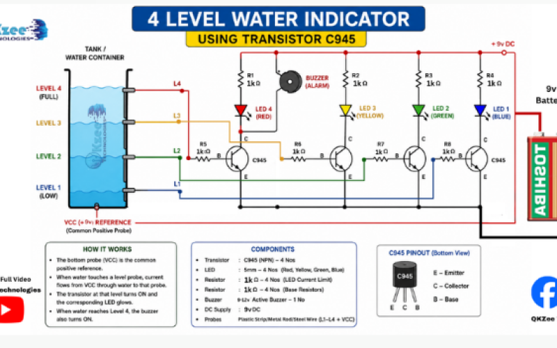
If you are searching for an easy school science project using a transistor, this 4 level water level indicator circuit using C945 transistor is one of the best beginner projects you can build in one evening. It looks impressive on a science exhibition table, it teaches real electronics concepts, and you only need a handful of cheap parts from any local electronics shop.
This guide from Qkzee walks you through the entire water level indicator project in plain, simple language — no confusing jargon, just clear steps a student can follow and explain confidently to teachers and judges.
A water level indicator is a simple circuit that tells you how full a tank, bucket, or container is — without you having to look inside. As water rises and touches different sensing points (probes), different LEDs light up to show the level: low, medium, high, and full.
In this 4 level water indicator project, we use:
This project is popular for school science fairs because it demonstrates transistor switching, water conductivity, and basic circuit design — all in one working model.
The C945 transistor is an NPN transistor commonly used in hobby and school projects because it is:
Water is not a perfect conductor, so the tiny current that passes through water alone is too weak to light an LED directly. This is where the C945 transistor becomes important — it acts like an amplifier switch. A small current from the water probe flows into the base of the transistor, and the transistor allows a much bigger current to flow from the battery through the LED. That’s the whole “trick” behind this circuit.
Think of your water container with 5 wire probes dipped inside at different heights:
Here is the simple logic:
Water acts as a natural conductor, closing the circuit between the common probe and each level probe. This tiny current triggers the base of each C945 transistor, switching on its connected LED.
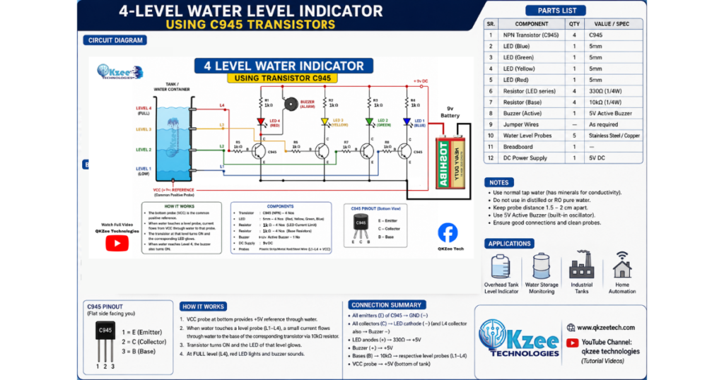
| Component | Quantity |
|---|---|
| C945 NPN Transistor | 4 |
| LED (Blue) | 1 |
| LED (Green) | 1 |
| LED (Yellow) | 1 |
| LED (Red) | 1 |
| 1K Resistor (for transistor base) | 4 |
| 1K Resistor (for LEDs) | 4 |
| 9V Battery | 1 |
| Battery clip with switch (on/off) | 1 |
| Breadboard | 1 |
| Jumper wires | As needed |
| Thin copper/probe wires | 5 |
| Plastic bottle or small water container | 1 |
Follow these steps carefully. Take your time — this is exactly how any beginner builds their first transistor-based water level indicator.
The C945 is an NPN transistor with three legs — Emitter, Base, and Collector (E-B-C when the flat side faces you). Getting this right is important, so double-check with a transistor pinout chart or the marking on the flat side before placing it on the breadboard.
Insert the 4 C945 transistors in a row on your breadboard, leaving enough space between each one so the LEDs and resistors don’t overlap.
Connect a 1K resistor from the base pin of each transistor to a separate probe wire. This resistor protects the transistor and controls how much current flows into the base.
Connect each LED’s positive leg (anode) through a 1K resistor to the 9V positive rail. Connect the LED’s negative leg (cathode) to the Collector pin of its transistor.
Connect the Emitter pin of every transistor to the negative (ground) rail of the breadboard.
Take one more wire and connect it to the negative/ground rail. This becomes your common probe, which will sit at the bottom of the water container.
Tape or fix the 5 probe wires (1 common + 4 level wires) vertically inside your plastic bottle or container at different heights, from bottom to top.
Connect the 9V battery through the on/off switch to the breadboard’s power rails — positive to positive, negative to negative.
Switch the circuit ON. Slowly pour water into the container and watch the LEDs light up one by one — Blue, then Green, then Yellow, then Red — as the water level rises.
This simple transistor water level indicator isn’t just for school — the same concept is used in:
Mentioning these applications in your school project file is a great way to show practical understanding, not just circuit building.
Looking for affordable components for this Arduino project? Check out QKZee Technologies, an online shop in Lahore, Pakistan, offering the best components for students and DIY projects. Whether you’re looking for sensors, modules, or other electronics at a cheap price, they’ve got it all. Visit them at QKZeeTech.
Building a 4 level water indicator using C945 transistor, 9V battery, breadboard, and LEDs is one of the most rewarding beginner electronics projects for school students. It’s affordable, safe, easy to assemble on a breadboard, and teaches real concepts about transistors, resistors, and water conductivity — all while creating a working, colorful, eye-catching display for your science exhibition.
Follow this step-by-step water level indicator circuit guide from Qkzee, gather your components, take your time on the wiring, and you’ll have a fully working project ready to impress your teachers and classmates.
More easy, beginner-friendly electronics and science project guides like this one are available on Qkzee — check back for more simple circuits, DIY project tutorials, and school science fair ideas.
Yes, other small NPN transistors like BC547 can also work in this circuit, but the C945 is widely recommended for school projects because it's affordable and easy to find.
The base resistor limits current going into the transistor to protect it, and the LED resistor prevents the LED from burning out due to excess current from the 9V battery.
Without resistors, the LEDs may burn out quickly and the transistors can get damaged from excess current — always use the recommended 1K resistors.
It's possible, but you would need to recalculate resistor values for safety. For a school project, a 9V battery is simpler and safer to handle.
Water alone doesn't carry enough current to power an LED. The C945 transistor amplifies this weak signal so the LED can turn on properly — this is the main learning point of the project.
Yes, you can connect a small buzzer in place of, or along with, the Red LED circuit so it sounds an alert when the water reaches the top level.
Yes, this 4 level water level indicator using C945 transistor is one of the most popular and appreciated school science projects because it's visual, functional, and easy to explain.
Simply say: "Water conducts a small current between two probes, which switches on a transistor, and the transistor lights up an LED to show the water level" — that's the entire working principle in one line.